Course:VANT151/2023/Capstone/APSC/Team5
Home
Welcome
You have arrived at the dedicated wiki page for Team 5 of VANT 151, a group of thirteen dynamic freshmen hailing from the Vantage Applied Sciences program at the University of British Columbia. Our primary endeavor was to develop a project focused on designing and constructing a miniaturized prototype of an energy-recovery laundry dryer, referred to as the EneRec Dryer. Here, you will find detailed documentation of our design journey, as well as comprehensive information about the final prototype design.
Introduction
The government of British Columbia initiated energy efficiency policies in 2018 to address carbon emissions and promote environmentally friendly choices. One of the key objectives was to inspire the adoption of sustainable products. Traditional clothes dryers have been known for their high energy consumption and greenhouse gas emissions, presenting an opportunity for improvement[1].
Our project focuses on developing a reduced-scale prototype of an energy-recovery clothes dryer that reduces energy usage and enables thermal energy recycling. By utilizing components and tools provided by the University, we aim to enhance heat transfer within the dryer, facilitating the recycling of thermal energy. This aligns with the sustainability principles and goals advocated by the BC government, contributing to environmental preservation efforts.
The project duration spans eight weeks, from May 18, 2023, to July 10, 2023. Our thirteen-member team is divided into six specialized sub-teams: Documentation, Electrical, Mechanical, Structural, Thermal, and User-interface. Each sub-team has specific roles, processes, and outcomes, which will be elaborated on in subsequent sections. A Gantt chart is included in the appendix, providing a visual representation of our timelines and work plans. The concluding section offers brief biographies of all team members for reference.
Team Requirements
Problem statement
Our design is aimed at tackling a salient issue that currently plagues the home appliance industry:
A prominent issue with many standard dryers present in the market today is their excessive energy consumption. These appliances function by persistently heating fresh air, transforming it into hot air, and then expelling it after a single cycle. This method not only results in substantial energy wastage but also negatively impacts the environment. Our initiative is to bridge this gap by developing a solution that's both energy-efficient and environmentally conscious, paving the way for a new generation of sustainable household appliances.
Functions
We have decided to use the drum to contain the clothes. Overall, the prototype should be able to:
- Incorporate an alphanumeric LCD display and navigation buttons.
- Easily adjust both drying time and temperature.
- Ensure even heating of clothes within the drum from all directions.
- Heat fresh air and ventilate stale.
- Move fresh air into the interior and expel stale air out of the prototype.
- Maintain a temperature inside the prototype that is higher than the outside temperature while ventilation is occurring.
Objectives
Our design aims to attain the following general goals as effectively as possible:
- Minimize the drying time for a cotton handkerchief.
- Maximize energy recycling.
- Reduce gas emissions.
In addition to these, we're also aspiring towards several other objectives:
- Implement a user-friendly interface.
- Ensure that the device operates as quietly as possible.
- Aim for durability and longevity of the appliance.
Constraints
The EneRec Dryer must adhere to the following necessary specifications:
- The dryer should be capable of completely drying a 15 x 15 cm cotton handkerchief within an hour.
- The overall dimensions of the dryer should not exceed 250 x 220 x 300mm, and the drum should have a maximum capacity of 0.5 L.
- It should have an electrical power consumption rate of 12 V AC and 12 VA.
- The design should be completed and ready within an 8-week development timeframe.
About Us
Our team comprises 13 members, strategically distributed across five distinct sub-teams. Each sub-team has been allocated specific roles and responsibilities, as detailed below:
- Documentation Sub-team: Comprising two members, this sub-team is responsible for preparing the gantchart, recording the work, and creating the PowerPoint presentation to effectively communicate our project.
- User-Interface Sub-team: This sub-team, also consisting of two members, handles programming operations and establishes the electrical connections, ensuring an intuitive and user-friendly interface.
- Mechanical Sub-team: Two members constitute this sub-team, tasked with managing the drum drive, creating 3D designs, and overseeing the heat exchanger design to ensure the functional and efficient operation of the dryer.
- Electrical Sub-team: This sub-team is comprised of three members, who are entrusted with crafting the electrical structure, implementing the heater, and carrying out essential programming tasks to ensure the appliance's energy efficiency and safe operation.
- Structural Sub-team: Also made up of two members, this sub-team is responsible for the overall structure design, ensuring the dryer is robust, reliable, and visually appealing.
- Thermal Sub-team: The final two members are part of this sub-team, focusing on thermal management within the dryer, contributing to its energy-efficient operation.
Each sub-team's specific duties and contributions ensure a holistic approach to the design and development process of the EneRec Dryer.
User-Interface Design
The User-Interface sub team is responsible for assembling and coding Arduino components to connect the operation of the dryer with the user in a intuitive way.
Requirements
Functions
The User Interface sub-team circuit aims to function in way that gives the desired output by constantly monitoring the inputs. This includes a working LCD, registering button inputs, proper display of messages in LCD as per the user’s convenience.
Objectives
- Intuitive user interface
- Inclusive user interface
Constraints
- Must use a LCD with size of 20x4
- Must use buttons
- Must use a maximum of 5 buttons
- Must offer choices to the user
The Design
Hardware

Layout

Program Flowchart

The primary objective of this sub-team is to establish a favorable and stable 5V voltage working environment for the UI sub-team by utilizing the RC circuit powered by the pin header and rectifier. Furthermore, the sub-team aims to enhance the hardware support for the thermal sub-team by implementing a heating sequence using modules such as motor, heater, and fan, ensuring durability. Moreover, this sub-team has thoroughly examined the placement of the Breadboard to minimize the circuit's space requirements within the project. This placement enables the mechanical sub-team to have ample space for accommodating the gear module, facilitating their works effectively.
Electronic Design
Requirements
The primary objective of this sub-team is to establish a favorable and stable 5V voltage working environment for the UI sub-team by utilizing the circuit powered by the pin header and rectifier. Furthermore, the sub-team aims to enhance the hardware support for the thermal sub-team by implementing a heating sequence using modules such as motor, heater, and fan, ensuring durability. Moreover, this sub-team has thoroughly examined the placement of the Breadboard to minimize the circuit's space requirements within the project. This placement enables the mechanical sub-team to have ample space for accommodating the gear module, facilitating their works effectively.
Functions
1.Motor: Powers the drum rotation and drives other components in the dryer.
2.Heater: Generates heat to raise the temperature of the air circulating in the dryer, aiding in drying the clothes.
3.Fan: Circulates air inside the dryer, helping to evaporate moisture from the clothes and expel moist air.
4.Sensor: Monitors conditions such as moisture levels and temperature, allowing for efficient and safe drying by adjusting drying time and preventing overheating.
Objectives
1. Assemble a stable circuit system to ensure the continuous range of electrical appliances.
2. Enable users to freely adjust the temperature inside the dryer.
3. Allow users to adjust the ambient humidity inside the roller.
Constraints
1. Safe 5 Voltage to prevent damage to Arduino.
2. Limit the temperature inside the dryer to a maximum of 75 degrees Celsius.
3. Limit the maximum power supply of external circuits to 24VAC.
The Design
Power Supply
| Choice 1 | Choice 2 | |
|---|---|---|
| AC | DC | |
| Response speed | 1 | 3 |
| Safe | 2 | 1 |
| Power efficiency | 1 | 3 |
| Total | 4 | 7 |
According to the decision matrix, the DC is the best choice as the power supply in this project due to fan, motor, and sensor all can connect with DC. However, AC can be applied to the heater.
There is the method for changing AC to DC.
1. Rectifier: A rectifier is used to convert AC voltage to DC voltage. There are two commonly used types of rectifiers: half-wave rectifiers and full-wave rectifiers.
This project used full-wave rectifier: A full-wave rectifier uses a bridge rectifier circuit, which consists of four diodes arranged in a bridge configuration. This configuration allows both the positive and negative halves of the AC input to be converted to DC. The output of a full-wave rectifier is smoother compared to a half-wave rectifier.
2. DC-DC SMPS: Once the AC voltage is rectified to DC voltage, a DC-DC SMPS can be used to further regulate and convert the voltage to the desired level. Step-Down (Buck) Converter: A step-down converter, also known as a buck converter, is used to reduce the voltage level. It utilizes high-frequency switching to efficiently step down the voltage from a higher level to a lower level.
3. RC Filter: Connect the RC filter circuit to the output of the DC-DC SMPS. The RC filter consists of a resistor (R) and a capacitor (C) connected in series or parallel. The RC filter helps smooth out any remaining ripple or fluctuations in the DC voltage, providing a more stable output.
- Once the high-voltage AC passes through the three electrical components above, it will be converted into stable DC.
Motor Control
In this project, the drum's kinetic energy is primarily generated through the collaboration of a motor and gears. To achieve long-term stability in motor operation, the electrical group is responsible for establishing a reliable circuit connection. In order to maintain precise control over the motor, it is essential to utilize Arduino's high-frequency program control (analogWrite).
By integrating Arduino's high-frequency program control into the circuit, the electrical group can effectively regulate the motor's speed, direction, and other operational parameters. This level of control enhances the overall controllability of the motor, ensuring optimal performance and enabling the desired functionality of the drum in the project.
It is worth mentioning that the E sub-team assisted the mechanical sub-team in using the motor as the power source to drive the drum to rotate through gears. After a series of tests, our sub-team found that the degree of engagement between the motor and the gear was sufficient to allow the motor to use the highest speed (90RPM)

Heater Control
The heater plays a pivotal role in the overall system as it is responsible for heating the interior of the dryer to achieve a desired and suitable temperature. Its primary function is to evenly distribute heat throughout the dryer's interior, ensuring consistent and effective heating.
Fan Control
To prevent overheating of the heater, the fan is used to control the internal temperature of the system. Temperature sensors will be connected in parallel in the circuit to detect temperature changes in the system. Combining two circuit components can maintain a constant temperature of the dryer as much as possible.
Sensor Control
| Choice 1 | Choice 2 | Choice 3 | |
|---|---|---|---|
| DHT11 | DHT22 | AM2320 | |
| Cost | 2 | 1 | 3 |
| Controllability | 2 | 3 | 1 |
| Simplicity | 1 | 3 | 1 |
| Total | 5 | 7 | 5 |
According to the decision matrix, the DHT22 is the best choice as the temperature/humidity sensor in this project.
Although it is more expensive, the only three programmable pin settings make it easier to set, and its code is easier to learn for engineers. The most important thing is that the reaction speed of DHT22 to temperature/humidity changes is faster.
Our group has chosen to place the sensor at the entrance of the drum, so that the environment inside the drum can be accurately detected.

Extra Feature
The extra feature of E sub-team is wireless control
| Choice 1 | Choice 2 | |
|---|---|---|
| WIFI | Bluetooth | |
| Cost | 1 | 3 |
| Controllability | 1 | 2 |
| Simplicity | 1 | 3 |
| Total | 3 | 8 |

According to the decision matrix, the Bluetooth is the best choice as the device for wireless controling in this project. Additionally, we chose the HC-05 Bluetooth connector because it is very cheap.

The manu of the bluetooth provides many options, including but not limited to querying temperature, querying humidity, pausing...
If the user enters the corresponding number, the dryer will also respond accordingly. Possible application scenarios are: if the user accidentally puts important items into the dryer, such as a phone, wallet, etc., the user can use the Bluetooth system to immediately stop the player and remove the item.
Performance Results
| Suggested Voltage | Actual Voltage | |
|---|---|---|
| Motor | 4.5V DC | 4.94 VDC |
| Fan | 9V DC | 8.7V DC |
| Heater | 12V AC | 11.38V AC |
| Sensor | 5V DC | 4.87V DC |
| LCD | 5V DC | 4.95V DC |
| HC-05 | 5V DC | 4.75V DC |
These results shown us that our electrical components are work correctly, the voltage of those electronic components fluctuates within a safe range, ensuring that the power in the circuit does not suddenly decrease and also ensuring the lifespan of the receiver.
Recommendations
There are several improvements that can help the EE team better complete this project:
1. The running time should not be too long to avoid damage to circuit components, and it can also extend the service life of the LCD.
2. During soldering, attention should be paid to whether there is short circuit, because the soldering rod is also metal and has strong conductivity. If the soldering rod is accidentally liquefied and dropped to other parts of the Breadboard during welding, it is very easy to have short circuit.
3. Before connecting real circuit components, it is important to use any method to calculate the voltage passing through this component (Tinkercad), as circuit components are easily damaged by high voltage. Simultaneously, important circuit components can be connected in parallel with suppressor diodes for protection.
Control Programs
After the UI sub-team obtains the temperature, humidity, and time required by the user through LCD and buttons sequences, this data will be provided to the heating function of E sub-system in the form of global variables. This function prioritizes starting the motor and fan because they do not need to be stopped during the heating process. However, if the sensor detects that the temperature inside the drum is higher than the user's desired temperature, the heating function will temporarily turn off the heater. Conversely, if the sensor detects that the temperature inside the drum is lower than the user's desired temperature, the heating program will turn on the heater again.
In addition, the Bluetooth system uses a pointer array to control the heating function. If Bluetooth information is captured during the heating process, HC-05 will compare the captured Bluetooth information with the pre-provided manu and make corresponding responses. Due to the fact that Bluetooth pointers can be used to control any memory data, it is theoretically possible to interrupt any function at any time using the Bluetooth system. However, in this project, the Bluetooth system is only used to interrupt the heating function.

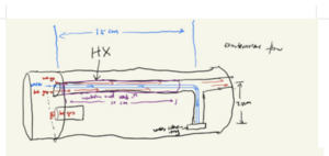
Overview of the thermal sub-system
Requirements
The thermal sub team is mainly responsible for the heat transfer part of Energy Recovery Dryer, including heat exchanger, heat outlet and water collection tray. The purpose of these components is to provide a space for the exchange of hot and cold air and hot and cold water vapor by connecting the outside to the drum. Flow-simulation is used to calculate and control the volume temperature and flow rate of the gas and water vapor in circulation.
Functions
- Heat exchange: The place for exchanging gases and vapor.
- Water collection tray: The place for collecting hot water from drum.
- Seals/insulation: The part is used to avoid hot air leaks.
- Flow-simulation: The controlled circulation of gases and water vapor occurs within this place.
- Cupper tube: The space for the circulation of water vapor
Objectives
- Heat recovery
- Long life span
- Easy to clean and replace the heat exchanger
- Non-toxic materials
- Compactness and space efficiency
Constraints
- User requirements
The first draft - Low Cost
- Space limitations cannot bigger than 20cm*15cm*15cm
- The melt point of material must higher than highest temperature for dryer

Heat is necessary for the efficient operation of the dryer
The Design

Heat Exchanger Type
| First Draft | Second Draft | |
| Heat dissipation efficiency | Higher | Lower |
| Suitable to Dryer | It can connect withe the LED | It can not connect LED |
| Separate heat and water | Easy | Hard |
| Choice | Better |
Heat Exchanger Top
The heat exchanger Top is positioned on the Heat Exchanger, serving the primary function of ensuring the collection of all water vapor into the Water Collection Tray. This guarantees the unhindered operation of the circuit by preventing any interference caused by the water vapor.

Water Collection Tray
The water tray, located at the bottom left of the heat exchanger. Its purpose is to collect the condensed steam generated by the heat pipe. The condensed water travels along the heat pipe to the water collection tray.

Seals and Insulation
This is a measure to prevent heat loss. It can be anywhere in the dryer.

SolidWorks Flow Simulation
The flow simulation demonstrates the manner in which the velocity of gas and vapor traverses the heat exchange process and affects temperature distribution. It is crucial to note that the maximum temperature must not exceed 450K, while the average temperature should ideally be around 328K.

The following link is the video for flow-simulation:
Structure Design
Requirements
The structural team is tasked with working on various aspects of the dryer, including the enclosures ,openings/holes, doors & latches, water collection tray and to design the LCD screen and the buttons place for the user interface (UI) parts.
The enclosure serves as a unified unit that contains and connects all the parts of the dryer. It encompasses the necessary openings, doors, and latches, as well as the appropriate placement for buttons and interfaces. To showcase the functionality of the enclosure, an animation illustrating the door movements is required. All of these requirements will be fulfilled through CAD design.
Functions

The overall framework are designed by the structure sub-team, which aimed for the functions include:
- The door which make sure the clothes not to fall out.
- LCD screen and buttons for user to operate the machine.
- By using water collecting tray to collect the large amount of water while the dryer is working.
Objectives
For the design goal of our cloth dryer, is to make a dryer shell (include door opening, water collection tray, LCD and the bottons). Meanwhile, the design should obey the requirements for ergonomically convenient and safety to human body.
- The cloth dryer is designed with excellent ergonomics and is effectively saving space
- The Location for LCD display and buttons are easy to see and convenient in manipulation
- The water collection tray offers a generous amount of space for efficient water management
Constraints
The dimensions of all parts and shells are restricted by the size of the materials used. The shell need to design an optimal scheme depending to the size of the given materials, and the inner part in the machine is depending to the final shell size.
- The size of the EneRec Dryer cannot exceed 250 x 220 x 300 mm.
- The dryer is not easy for carry
- The cost for the dryer is cannot be too expensive
- It is essential to maintain the temperature below the maximum heat resistance of the material
The Design
Aluminum Frame
The subteam members have drawn the sketch of aluminum frame and all the components in it, it is the fundamental part for the cloth dryer, the measure of length and the utilize for the space are all depending on the size of the aluminum frame.
It contains two 190 × 190 mm glasses, two 270 × 190mm glasses, two bottom plates and several aluminum sticks.


Enclosure
Here's the three-view diagram of the design:


The front view for the dryer contains active trapdoor that user can conveniently put the washing clothes in, beside the trapdoor there is a place for buttons and LCD screens as for the operation process. To fixed the door of this dryer, latch is set next to it.
As for the right view of the dryer, there is a place under the right corner to collect the exceed water, which is the place of water collection tray set in.
Opening & Hole
There are two sets of plan due to the design of the structure subteam:


The center hole's diameter is 100mm and each screw hole is 5.56 mm.
| Plan A | Plan B | |
|---|---|---|
| aesthetic | 1 | 2 |
| cost | 2 | 1 |
| stability | 1 | 2 |
According to the decision matrix, Plan B is the best choice due to its appearance and stability.
Althrough Plan A is cheaper than B, there is only the difference in the usage of the screw so it is not really matter.
Door & Latches
The circular glass which been cutted can perfectly fit to the center hole, therefore, after some decoration by the laser cut, the circular glass can bind with latch and can be normally use as the door of the dryer.
Here is the sketch for the circular door:

Water Collection Tray
The original sketch of the water collection tray was designed as 40 × 26 mm rectangle at the bottom-right corner of the glass board.

However, the actual size for the tray is a little bit larger, therefore there wasn't any enough room for the tray. To solve the problem, one of our team member do the laser cutting again, this time, the width of the rectangle had extended to 57mm (near to the edge of the glass). This time, the tray can fit well.
LCD Screen & Buttons
Here's the sketch for the top panel hole:

It's the hardest one because it contains lots of data and need to cut several holes. Luckily, our team members are willing to challenge. By communicating with UI subteam, we got a list for every hole size.
| Part | size/mm |
|---|---|
| LCD screen size | 95 × 38 |
| Screw hole diameter | 5.56 |
| Button hole diameter | 11 |
| Speaker hole diameter | 30 |
| Sepration between LCD screen and screw hole | 6 |
| Sepration between buttons | 16 |
After all the preparation works are done, the assemble process is taking place.
Mechanical design
Requirements
The mechanical subteam designs, manufactures and evaluates mechanical components of the Dryer Machine and adheres to specified requirements and limits.
The team needed to make a drum drive that make the drum to rotate, and some 3D printed parts to support other components.
Functions
A. Drum drive: Device that drives drum rotation by a motor.
B. Sensor mount: A bracket for fixing the sensor.
C. Breadboard mount: A bracket used to protect the breadboard from shaking due to machine movement。
D. Motor mount: A bracket used to secure and protect the motor
Objectives
- Design a Drum Drive that rotates efficiently to ensure that laundry can be dried
- Design the mechanical components inside the dryer machine to ensure that they can be assembled.
- Choose the right location for your mechanical components to ensure efficient layout.
- Limit the power as much as possible to ensure energy savings
Constraints
Minimum capacity of 0.5 L (capable of drying a 15x15cm cotton handkerchief within an hour).
- The dimensions of the components must be 250x220x300 mm.
- The motor should be supported by a motor mount.
- The sensor holder must be compatible with the sensor design.
Drum Drive Mechanism Design Alternatives
The main components of the dryer drum mechanism are the drum itself and the motor. The motor is used to rotate the mechanism of the drum, which is used to store clothes that need to be dried. With this concept in mind, different ideas have been drafted for this mechanism.
The following two diagrams,Figure 6.1 and Figure 6.2 are the two scenarios we came up with. Figure 6.1 is the adopted scenario and Figure 6.2 is the alternative option. Although both drum drives rotate the drum through the motor drive gear, we prefer to use the second one. Although the gear set of the alternative scenario allows the drum to rotate faster and more efficiently, it requires more space and requires more material to create brackets for the two gears located next to drum. Therefore, considering the layout of the machine and other factors, the scenario shown in Figure 6.1 was chosen.


Evaluation
| Plans | Advantages | Disadvantages | comments |
|---|---|---|---|
| The applied drum drive (Shown in Figure 6.1) |
|
|
|
| The alternative drum drive
(Shown in Figure 6.2) |
|
|
Compared with these two solutions, in fact, we think that the alternative plan is more ideal because of its high efficiency and more design. However, due to space layout limitations, we had to swap out this scheme and use two helicle gears with smaller size to drive the drum rotation.
After communicating with the structure subteam, the second option was finally chosen, which is to use the drum drive shown in Figure 6.1.
Basic Features
1. Drum Drive
2. Breadboard Mount
3. Motor Mount
4. Sensor Mount
5. 3D Print Parts


1. Drum Drive
The power transmission device provides the core driving forces to prompt the drum to rotate, as shown in Figure 6.1. To assist with drum rotation, we designed a ring at the front and rear ends of this cylinder made of aluminum sheets, as shown in Figure 6.3. At the rear ring, there is a gear with a number of 88 teeth and a diameter of 110 mm. This gear will bite the gear that is sheathed to the motor that shown in Figure 6.4 and rotate by providing power through the gear on the motor. The rectangular hollow in the middle of the helical gear can tightly fit in with the rotating shaft of the motor. The motor speed is 140 rpm, and under the action of the gear set, the drum speed can reach almost 40 rpm, and with the assistance of Air Flow, the clothes can be effectively dried.
2. Motor Mount

A motor mount is used to securely attach and align an electric motor, minimize vibrations, absorb shocks, ensure stability, and enhance overall performance, protection, and longevity of the motor and the system it is a part of. Considering the high speed of motor rotation, to protect the motor and sustain the whole system steady, it is necessary to have a mount to reduce the vibration from it. The motor mount is placed at the corner of dryer and in doing so it can maximum reduce the potential damage that may bring to the system and improve the life time of dryer.
3. Breadboard Mount
By using a breadboard mount, which is shown in Figure 6.6, we can position the breadboard at a comfortable working angle, making it easier to insert and remove components, connect wires, and troubleshoot circuits. The mount also helps organize the workspace by keeping the breadboard in a fixed position, reducing the chance of accidental disconnections or damage to the circuit.
4.Sensor Mount
A sensor mount is a device that securely holds and positions sensors, as shown in Figure 6.7 Its primary functions are to provide stability, protection, and accurate positioning for sensors. Sensor mounts ensure that sensors remain stable, aligned, and protected from external elements. They also facilitate integration into larger systems, manage cables, and may offer adjustable parameters for optimal sensor orientation. In summary, sensor mounts optimize sensor performance and reliability in various applications.
5.3D Print Parts
In this semester, components such as front ring, rear ring, motor gear, motor mount, breadboard mount and sensor mount were successfully designed and printed as shown in Figure 6.1, 6.3, 6.4, 6.5 6.6 and 6.7.
Recommendation

During the run, the drum can spin at the expected speed. And the mount used also successfully fixed these components.However,in our final demo, we found that the gears would occasionally disengaged with the back rings which lead to the whole system paralysis. The reason behind this is that the motor could not perfectly fit into the sensor mount due to design error, which let the friction between gears and back ring slowly shift the position of motor mount and make gear disengage with back ring. The solution to this problem is to design a unique attachment between motor mount and motor.
Appendices
Gantt Chart
Here is the gantt chart for all subteams. Everyone in the our group followed this ganttchart.

SolidWorks Sustainability Report
Although the materials used in the 3D printing (PLA) and for constructing the boards (acrylic) are fixed, consideration for environmental impact and sustainability is vital. If given the opportunity to undertake this project again, we would like to use acrylic for the 3D printing and PP Copolymer for the board materials. Below is the sustainability report for these materials:
- File:Sustainability report for changing Acrylic to PP Copolymer.pdf
- File:Sustainability report for changing PLC to acrylic.pdf
- File:Sustainability report.pdf
PDF Drawings
Assembly drawing:
Total render:
Part renders:
- File:0a92c2cebc0c6a7607fbc296038236f.jpg
- File:0f99ee9b174758d30abb2da96adb7fb.jpg
- File:3f0b33cbcda73e2eace7a914f36c9be.jpg
- File:35a1e3af6d1ac2c819934a63a9d37d9.jpg
- File:C2bbe202422ccd088b4dac7db942414.jpg
- File:C4bbd17feb2ec7eaaf68ce8ace4def6.jpg
Ardunio code
This is the code written by Electrical sub-team and User-Interface sub-team:
References
[1] "Policy, Regulations and Bylaws - Province of British Columbia," Government of British Columbia. [Online]. Available: https://www2.gov.bc.ca/gov/content/industry/electricity-alternative-energy/energy-efficiency-conservation/policy-regulations. [Accessed: 13 June 2023].
About us
We are a group of 13 international students from around the world, uniting 11 individuals from various regions of China, one from the vibrant landscapes of Brazil, and another from the historic depths of Syria. This unique blend of backgrounds and perspectives has enabled us to synergize effectively, culminating in our proud achievement: the invention of the EneRec Dryer.

Sub-teams
| Document | |
|---|---|
| Boyuan Zheng (77464600)
Document sub-team member  Hailing from Zhengzhou City, Henan Province, China, I am an international engineering student with a keen interest in web design, article writing, and the various aspects of science. Recently, I was actively involved in a project where my contributions included creating the project's website, developing comprehensive Gantt charts for effective team coordination, generating illustrations, and providing 360-degree rendered images. Additionally, I extended my support to other sub-teams, such as Structure and Thermal, during the project. As I plan to delve into electrical engineering in my second year at UBC, I find the knowledge and skills acquired from this course incredibly beneficial for my future studies. Among my accomplishments in this project, I take particular pride in the successful creation and implementation of the Gantt chart, as well as the design of a visually appealing website. |
Tianyu Wu (96355094)
Document sub-team member  Hi! My name is Tianyu Wu from Shanghai, China. I am an international student who prefers to use my hand to create new technology to give people a more convenient life. In VANT 151 class, I joined Documental to work on the assembly of our dryer and render in Solid Work app, make our team power points and arrange each sub-team Gantt Chart. It was an incredible experience, combining the thrill of hands-on creation with the satisfaction of contributing to the advancement of technology. I look forward to undertaking more challenging projects in the future, pushing the boundaries of innovation and creating solutions that positively impact people's lives. |
| Electrical | |
 Electrical sub-team member & Group leader. My main responsibilities revolve around code programming and implementing additional functions. For me, I am very interested in the field of Electromagnetism. This project provides me with an excellent opportunity to explore and deepen my understanding of this field. Therefore, the rich knowledge I have gained in this job is very valuable. Before proceeding with this project, I believe that any given circuit can be constructed using only basic components such as resistors and capacitors. However, this course exposed me to a new world of advanced circuit components. Specifically, I have gained a comprehensive understanding of the functions and significance of components such as MOSFETs and transistors, which play a crucial role in the successful implementation of the project. These newly discovered knowledge not only broadened my technical expertise, but also stimulated my enthusiasm for further exploration in the field of Electromagnetism. |
 Electrical sub-team member Come from Chongqing city, China. I have a keen interest in electronic components and plan to study electronic engineer in my second year. So I chosen electrical sub-term in this project. During this project, I was mainly be responsible for tasks related to electronic components. At the beginning, some electronic components in our toolbox was broken such as fan and motor, to was me to fix the fan and the fix motor within the help of Doctor Goh cause those electronic components do not have any spare ones, I also connected wires to the plug and participated connected the circuit. Unlike other sub-term such as structure sub-term whose components are hard to broken. Electronic components are fragile, any minor poor contact in some small areas can lead to the entire circuit being unable to function. Every time when some electronic components could not work I would come to fix. I learned a lot from this project. I became more proficient in coding and connecting the circuit and gained expertise in soldering techniques. Most importantly, I realized that an engineering project is a continuous process of discovering discrepancies between ideas and reality, and finding ways to resolve them. |
 Electrical sub-team member I'm Xiangrui Yin and I'm from Hunan, China. I love new things and I always put the most time and energy into the things that interest me. Since I am good at electrics, I oversee the electrical section of this project. During VANT151, I learned a lot of skills that I had never been exposed to before, and I was exposed to long-term collaborative projects for the first time. It was a wonderful experience. |
|
| Mechanical | |
 Mechanical sub-team member My name is Zhen Tang and I am from Hunan, China. I have a very strong interest in the field of engineering, especially in mechanical engineering and electrical engineering. I love designing things because I think I have a lot of interesting and even whimsical ideas, so I want to study engineering to give me opportunities and develop the ability to realize my ideas. I had the opportunity to do a lot of 3D modeling in this project, and although I encountered many setbacks along the way, I never gave up and learned a lot of lessons. I hope to have such an open mind in my future studies and strive to learn knowledge to achieve them. |
 Mechanical sub-team member Hello everyone! My name is Quanjin Li and I am currently a Vantage One Engineering student. In VANT151 project, I am responsible for design the device on Solidworks and print it on the 3D Printer. I personally have a keen interest in mechanical design since I enjoy the accomplishment of building perfect parts of device. What makes me have such a huge passion about engineering is that I can learn the theorem I need and practice it in the real word to make value. I think I will continue to keep my enthusiasm in my future learning path. |
| Structural | |
 Structure sub-team member Hi, my name is Xuhang Wang, I come from Suzhou, China. In this project, my job was to assemble all the parts of each team, and to design and arrange their distribution to make the whole team more coordinated. I am very interested in painting and design and have strong practical ability. Structure gave me a good opportunity to show my strengths, including assembly and planning. For me, assembly is an interesting process, especially in the absence of specific drawings. It is not just an assignment, but a challenge and proof for the whole team. I am grateful for the efforts of other team members. I will work harder to be a qualified engineer in the future. |
 Structure sub-team member Hi, my name is Wu Li, I come from Wuhan, China, and now across far distance to Vancouver for studying. I am currently an vantage student. In this project, my job is to create the sketches of different shapes on the glass by using the SolidWork, then transfer them to the PDF form and do the laser cutting. I enjoy these operations so much and I have learned lots of experiences due to the create. I will keep my enthusiasm and do well in the future class. |
| User-Interface | |
Sam (51469112) User-Interface member My name is Sam Rezeq, and I have come a long way from Syria to Canada to pursue my dream major. I am incredibly passionate about engineering and, specifically, the field of user interface design. Choosing to be part of the user interface subteam was an easy decision for me because it is where the real action happens. It is here that users can fully utilize all the features of the machines designed by engineers like myself. What drives my passion as an engineer is the opportunity to understand and cater to human needs. It is a humbling experience to realize that our work has the power to shape and satisfy those needs. By designing intuitive and user-friendly interfaces, we can enhance the overall experience for individuals interacting with technology. The satisfaction of witnessing my creations come to life and positively impact users' lives is truly fulfilling. Moreover, my personal background has played a significant role in my dedication to engineering. Having experienced different cultures and contexts, I understand the importance of adaptability and considering diverse user perspectives. This has further motivated me to create solutions that cater to a wide range of needs, ensuring inclusivity and accessibility in my designs |
Lina Meneghin Naleto (26359976) User-Interface member I am an international student from Brazil. I started to get interested in programming and arduino in my school's robotics team when I was 14 years old. Since then I went to college in systems development to specialize in programming and developed a lot of projects. Doing this project in the user-interface sub-team just proved that it's an area that interests me a lot and it was a great experience to learn more about it. |
| Thermal | |
|---|---|
 Thermal sub-team member My name is Jianqiao Peng, and I am from China. I am currently a student at Vantage. In our ongoing project, my primary responsibility is to analyze and design crucial components of our dryer, including the water collection tray and heat exchange top. Throughout this project, I have gained valuable experience in utilizing 3D printers and SolidWorks software. This hands-on experience has been immensely beneficial, allowing me to enhance my communication skills and practical expertise while collaborating with diverse team members. I believe that this course will greatly contribute to my future studies and professional endeavors.
|
 Thermal sub-team member My name is Jingchen Zhang.I'm an international student from Shandong Province, China. My father is an engineer so I choose Apply science in UBC. I'm a Thermal-sub-team member because I'm interested in the thermal conductivity of materials. I was responsible for most of the 3D printing of over sub-team and also I design the flow-simulation for the dryer. |