Course:VANT151/2023/Capstone/APSC/Team3
Home
Welcome
Welcome to the Wiki page of Team 3 of the EneRec Project. EneRec, or Energy Recovery Dryer, is our multidisciplinary engineering design project directed by Dr Ernest Goh in the VANT151 course. This Wiki Page contains our team's report of progression and final product in designing cloth dryers with our innovation.
Thank you to all the group members as contributors to the Wiki page and the entire project.
Introduction
Based on the experiences of both users and manufacturers, it has been observed that the conventional design of clothes dryers consumes a substantial amount of energy. This issue is primarily due to the prolonged heating of air and the utilization of hot air for a single cycle, resulting in incomplete drying of clothes. In order to address this concern, our team proposes introducing the innovative concept known as the "Energy Recovery Dryer."
This project is to build a scaled-down prototype of a cloth dryer that maximizes the efficiency of energy during the drying process with fresh air from the outside and minimizes the energy loss to heating single use air, using the components and tools provided by the university, by 2023 June 28.
This project was carried out over eight weeks, from 2023 May 8 to 2023 June 28. Our project schedule is shown in the Gantt chart in this page's appendix. We organized our team of ten members into five sub-teams of two members each: electrical, mechanical, documentation, user interface and structural. We describe the work of each sub-team in the following sections. Brief biographies of members are found in the last section.
Team Requirements
Functions
Overall, the prototype should have basic function listed below:
- Alphanumeric LCD display for communication
- Accepting user inputs of temperature, time and humidity using buttons
- 2 drying modes (user manual custom and automatic)
- Pause function during the process
Objectives
By examining the scoring rubric of the prototype performance evaluation test, the prototype should achieve these objectives:
- Efficient energy recovery
- User-friendly
- Fast drying process
- High efficiency of drying process and low energy loss
Constraints
The prototype shall:
- Have a size that does not exceed 250 x 220 x 300 mm, ensuring it can fit within a carton designed for copier paper.
- Have maximum allowable electrical power consumption should be 24 V AC and 40 VA.
- Have a minimum capacity of 0.5 L.
- Be capable of drying a cotton handkerchief (15x15cm) within 1 hour.
- Have an automatic operating mode that can be used easily.
- Have a manual operating mode, allowing users to set desired parameters such as drying time, temperature, and dryness level.
- Be completed within 8 weeks.
- Be completed using limited tools and components.
User Manual Book
To make it easier for users to operate Enerec, please access our manual book through the link provided below:
https://www.flipsnack.com/AC9897BBDC9/enerec-guidebook/full-view.html

or scan the QR code
Conventional Dryer VS Sample EneRec VS Our Design

Mechanical Sub-team
Requirements
The mechanical sub-team members are responsible to:
- Determine the size (radius, height) of the drum → To reach 0.5 L volume of the drum
- Modify the 3D Printed Parts → Air Duct, Sensor Mount, Front Ring, and Back Ring
- Design the 3D Printed Parts → Motor Support, Gear, Heat Exchanger Cover, and Extra Feature
- Plan and Evaluate the Drum Drive system to be efficient
Functions
The following components and associated functions were made:
- A way to make sure the clothes are uniformly dry
- A way to ensure the temperature and humidity sensor can measure the level of dryness of clothes
Objectives
- Maximize the effectiveness of drying time
- Minimizing energy consumption
- Minimizing material usage
- Maximizing environmental friendliness
- Ensuring precise and accurate execution from another sub team
Constraints
- Minimum capacity of the drum: 0.5 L
- Size of the fabric that is intended to dry: 15 × 15 cm (± 3 cm)
- Maximum drying time: 1 hour
- All of the components and parts must fit in the frame dimension: 250 × 220 × 300 mm
- The motor support design should be compatible to the given motor
- The sensor mount must be compatible to the given sensor
The Design
Drum Size
The design of the drum is based on a cylindrical shape with baffles. The drum's inner diameter is 108.6, with a length of 72.5 mm. The total volume of the drum is 0.664 L. The baffles have a height of 14.5 mm. The front ring is designed to be attached to the three baffles to prevent air leakage between the baffles and the front ring. The hole for self-tapping the baffles and the back ring is designed to unify this ring and the baffles. Related to the number of baffles, three or four baffles are effective. Thus, a Weighted Decision Matrix was made to choose the correct number of baffles based on the effectivity and efficiency (Table 2.1).
| Aspect | Weight (%) | Design 1 | Design 2 |
|---|---|---|---|
| Design | - |  |
 |
| Simplicity to model and manufacture | 20% | 2 | 1 |
| Reduction in weight distribution to the front ring | 40% | 3 | 1 |
| Reduction in weight of the total baffles | 40% | 3 | 1 |
| Overall | 100% | 2.8 | 1 |
Equal weight distribution (40%) is given to the less weight distribution, and less weight takes to the total baffles since the drum rotation is more effective if the weight is not heavy. Simplicity to model and manufacture was assigned a weight of 20% as the design process does not matter, compared to the efficiency result. According to the WDM table (Table 2.1), three baffles are more effective than four baffles.
Drive System
A set of helical gears rotates the drum. The large gear has 57 teeth, and the small gear has 21 teeth. In terms of the diameter, the large gear has a 106.8 mm pitch diameter, and the small gear has a 37 mm pitch diameter. The large gear and the small gear ratio are approximately 1:3.
| Category (1-3) | Weight | Helical Gear | Spur Gear | Worm Gear | Belt and Pulley System |
|---|---|---|---|---|---|
| Efficiency | 25% | 3 | 4 | 2 | 4 |
| Manufacturing simplicity | 20% | 2 | 4 | 1 | 4 |
| Noise produced | 15% | 4 | 1 | 2 | 2 |
| Durabilty | 40% | 4 | 1 | 2 | 1 |
| Overall | 100% | 3.35 | 2.35 | 1.8 | 2.5 |
The weighted decision matrix (WDM) incorporates the perspectives of manufacturers and users in evaluating power transmission systems. Manufacturers emphasize manufacturing simplicity (20%) to achieve efficient production and cost-effectiveness. Users prioritize efficiency (25%) to ensure optimal power conversion and reduced energy costs. Additionally, noise production (15%) is a concern for users, as it impacts comfort and safety. Both manufacturers and users highly value durability (40%) to avoid the need for frequent replacements. By considering these factors, the helical gear obtained the highest score in the WDM, leading to its selection as the driving mechanism in the system.
Motor Support
The design of the motor support is illustrated in table 2.3. The oval-shaped hole on the top side of the support is used to accommodate the motor. The motor can be vertically positioned inside the container at the top. The four holes for the screws are designed to secure the motor support to the base. Based on the WDM below, design 1 is chosen as the support to be used. Design 1 emerges as the preferred choice due to its optimal size, low cost, simplicity of motor installation, and durability. It effectively addresses the requirements with its well-balanced performance, affordability, user-friendly installation, and long-lasting quality.
| Aspect | Weight (%) | Design 1 | Design 2 | Design 3 |
|---|---|---|---|---|
| Design | - |  |
 |
 |
| The size of bottom plane | 30% | 3 | 1 | 2 |
| A low cost | 10% | 3 | 2 | 1 |
| The simplicity of motor installation | 30% | 3 | 1 | 1 |
| The durabiltiy | 30% | 2 | 3 | 1 |
| Overall | 100% | 2.7 | 1.7 | 1.3 |
Heat Exchanger Top
As already mentioned, the heat exchanger is utilized to exchange heat between two or more fluids. In this EneRec Dryer, the heat exchanger will work upon the counterflow. The top of this heat exchanger is designed to give more support to the clear pipe and secure the heat exchanger. The 3D design of the heat exchanger top can be seen in Figure 2.6. In detail, the illustration of the heat exchanger top can be seen in Figure 2.8.

Temperature and Humidity Sensor
To improve temperature measurement accuracy, the sensor is placed inside the drum. The model of the sensor is AM2303. Specifically, the back of the drum is the plane of the sensor to be placed. Once the sensor is fitted to the hole of the modified air ducts, the sensor is drilled to fix its position. This strategy is arranged to establish the effective detection of the maximum temperature and humidity. Based on table 2.4, design 2 stands out as the optimal choice. Its placement of the sensor in the air ducts ensures accurate drum condition measurements while avoiding interference from crossing multiple components. Additionally, the shorter wire required by Design 2 simplifies the installation process. Thus, design 2 emerges as the preferred option due to its superior accuracy, minimal interference, and ease of implementation.
| Design 1 | Design 2 | Design 3 | |
|---|---|---|---|
| Design |  |
 |
 |
| Advantages |
|
|
|
| Disadvantages |
|
|
|
Electrical Sub-team
Requirements
Functions
- The program can dry the clothes based on the values of temperature, humidity, and time provided by the user interface
- A sensor that measures temperature and humidity and adjusts the intensity of the heater
- Ensure the safety of the process that prevents the user's profit
- The system stops when the user presses the emergency button
Objectives
- Maintain the temperature inside the drum depending on the user's choice
- Provide dry clothes with humidity based on the user's selection when the drying process finishes
- Getting the dryer to run as consistently as possible
Constraints
- The motor, fan, heater, and sensor were provided
- 250 x 220 x 300 mm size breadboard to fit all the components
- 24 VAC, 40 VA power consumption
- Maximum drying time: 1 hour
The Design
Power Supply
According to Figure3.1, the power supply converts 24V AC to 9V DC and protects against current surges using an array of capacitors. The 9V DC circuit powers the fan and Arduino Uno, whereas the 24V AC circuit powers the heater.
Fan Circuit
According to Figure3.2 The voltage used to power the fan is 9V DC. The fan system is connected to the Arduino Uno board through a PWM signal pin, which can control the speed and the rotation of the fan system in the Arduino. A MOSFET component is employed to switch and run the system to control conductivity in the fan system. The fan's rotation speed will be determined depending on the user's inputs. While in this process, the fan speed is set to achieve maximum efficiency, which manages heat flow as effectively as possible.
Alternative designs comparison
Mode 1: (Fixed Mid-Speed) The fan's speed will be fixed at a constant medium in this alternative design. While the fan is connected to the PWM pin in the Arduino board, it can be operated by sending a PWM value of "130" through an "analogWrite" operation.
.png)
Mode 2: (Fixed High-Speed) Like the "Fixed Mid-Speed" mode above, the fan's speed will be fixed at a constant high. While the fan is connected to the PWM pin in the Arduino board, it can be operated by sending a total PWM value of "255" through an "analogWrite" operation.
.png)
Mode 3: (Fixing-Speed based on the sensor) Unlike the two modes above, the fan's speed depends on input from the humanity and temperature sensor. The "analogWrite" will send a high PWM value to the fan pin if the Arduino board receives a high input value from the sensor and vice versa. If the humidity and temperature inside the drum are too high, the fan will operate faster while the temperature and humanity drop.
.png)
The three modes have been evaluated based on three leading indicators: drying efficiency, noise pollution avoidance, and stability.
| Weight | Mode 1 | Mode 2 | Mode 3 | |
|---|---|---|---|---|
| Drying efficiency | 60% | 5 | 2 | 3 |
| Avoidance of noise pollution | 15% | 3 | 1 | 4 |
| Stability | 25% | 4 | 4 | 2 |
| Overall | 100% | 4.45 | 2.35 | 2.9 |
Drum Motor Circuit
According to Figure3.3, The Arduino platform's PWM signal pin controls the drum motor, which is powered by 5V DC power. The MOSFET component is also utilized to switch and manage the circuit's load. Different inputs can be specified in the Arduino application to control the motor speed directly.
Heater
According to Figure3.4 A transparent isolator isolates the controller from the alternating current in the electric circuit, which powers the heater. This circuit is connected to the Arduino's PWM signal pin. The heater is powered by 24V AC electricity. In addition to the circuit component, the Arduino platform controls the heater. Because a sensor is connected to the circuit, the software can control the heater's operation based on the value supplied by the sensor.
Humidity and Temperature Sensor
DHT22 is a sensor to check the temperature and humidity in the entire system used during this project. The purpose of the DHT22 sensor is to determine the temperature and humidity inside the drum. As can be seen from the flowchart above, when the drum reaches the maximum level of temperature and humidity, the drying system will end and finish the drying process.
Alternative designs comparison
Mode 1: In this mode, the humidity and temperature sensor will be started to sense the humadity and temperature inside the drum when the overall system receives the instruction from the user-interface operation.
Mode 2: In this mode, the humidity and temperature sensor will be started to sensor the humidity and temperature inside the drum 1 minute after the overall system receives the instruction from the user-interface operation.
The two modes above have been examined based on four primary indicators: drying efficiency, energy efficiency, stability, and accuracy.
| Weight Percentage | Mode 1 | Mode 2 | |
|---|---|---|---|
| Drying efficiency | 50% | 1 | 4 |
| Energy efficiency | 10% | 2 | 4 |
| Stability | 15% | 4 | 4 |
| Accuracy | 25% | 0 | 4 |
| Overall | 100% | 1.3 | 4 |
Control Programs
The following flow chart illustrates the overall function of the electrical control on all the electrical components inside the dryer.
Figure 3.9 Flow chart of the electrical control system
Extra Feature (Door-lock detector)
Due to the concern for the user's safe operation and the dryer itself, a door-lock detector is considered for the dryer. A micro switch is used to detect the status of the dryer door. When the door is open, the microcontroller will be released to disconnect the circuit and send a low-voltage message to the Arduino board so that the system will not further function until the door is closed. On the other hand, when the door is completed, the micro switch will be pressed to connect the circuit sending a high-voltage message to the Arduino board so that the system can operate safely.

User Interface Sub-team
Requirements
The user interface is required to design a user-friendly and intuitive programme, allowing users to straightforwardly navigate the system’s functionalities, as well as designing the input and output hardware.
Functions
The user interface sub-team was responsible to :
- Display the appropriate messages on the LCD depending on the user's input
- Provide various options based on the user's demand
- construct a flexible algorithm for the user
- Design the most intuitive hardware
Objectives
The objectives of the user interface sub-team consist of the following:
- User-friendly (efficient and communicative)
- Customizable manual
- An efficient program with minimum delay
Constraints
- The screen is limited to 20x4
- Only string type of character that can be print
- The input model is qualified to button or wheel drive
- The UI internal hardware is limited to a single Arduino Uno and a large breadboard
- Each block in the LCD is limited to 5x8 pixels
The Design
Hardware Layout
a. Button layout
- The first alternative hardware interface design (model_1) utilizes three buttons on the right side of the screen
- Benefits: Less area needed, low cost, simple
- Drawbacks: Weighty codes
- The second alternative hardware interface design (model_2) utilize four buttons on the right side of the screen
- Benefits: Low memory needed, console inspiration, short-time usage
- Drawbacks: Higher cost
- The third alternative hardware interface design (model_3) utilize four buttons underneath the screen
- Benefits: Symmetrical, low memory needed, console inspiration, short-time usage
- Drawbacks: Larger area needed, higher cost,
- The fourth alternative hardware interface design (model_4) utilize four buttons underneath the screen
- Benefits: Symmetrical, android inspiration, low cost
- Drawbacks: Larger area needed
Table 4.1 Weight Decision Matrix of Alternative Design for Monitor and Button

The weighted decision matrix (WDM) incorporates the perspectives of the engineers that design the program and the users in performing the program. Engineers emphasize light memory (10%) because if a software program continues consuming the memory and is not freed, the program or the operating system may crash. The engineers also prioritize cost (30%) to help the decision-making process and control resources, such as the number of buttons. Furthermore, the cost is also a concern for the user. Both engineers and users are highly concerning the practicability (40%) to achieve the most efficient and communicative program. Additionally, engineers and users also emphasize the environmentally friendly (20%) of the design.
Based on the group discussion and analyzing process using this weight decision matrix, the final button layout decision was the idea with model 1 due to its user-friendliness, affordability, eco-friendliness, and aesthetic purpose.
Program Flowchart
Figure 4.1 Program flowchart of User interface sub-team 3
The program starts by displaying the welcoming message on the LCD, which will wait until the user presses any button. This input will initiate the operation and lead to 2 different modes, which are automatic and manual. The LCD will go through the ensuring process if the user uses the automatic mode. At this time, LCD will display the chosen mode and two options of response that can be selected by the user, which will be continued and back. However, supposing the user selects the manual mode, the LCD will redirect and present a customizable manual with the top and bottom buttons to drag the arrow and control the number to the desired point. The midpoint will confirm the decision and continue the ensuring process. In this ensuring process, the LCD will display the temperature and duration entered by the user. The LCD will change consistently depending on the input by the user. When the user has entered all the appropriate information and decides to start the drying process, the machine will begin to run. During drying, the user can stop the device whenever they want and determine whether to continue until the cycle ends or restart the program.
Operating Sequence
The program will be operated using three buttons and an LCD displaying the desired output depending on the user's input
- Yellow button: used to drag the arrow and increase the temperature or time in the self-entered process
- Black button: utilized to confirm the desired option chosen by the user
- White button: used to decrease the temperature or time in the self-entered process and drag the arrow
The ideas for the LCD option layout are shown in Figure 4.2.

The alternative design has progressed occasionally, and the chosen option is designed 3. This design has more complete menus offered to the users, and the flow of the program is also more organized.
The design was compared using the Pugh decision matrix by considering several significant aspects of the design flow.
| Design 1 | Design 2 | Design 3 | |
|---|---|---|---|
| User-friendly (simple and communicative) | 2 | 2 | 3 |
| Less button press required | 3 | 2 | 1 |
| Accurate customization menus | 1 | 1 | 3 |
| Organized and effective flow | 1 | 2 | 3 |
| Total | 7 | 7 | 10 |
The sequence of the programme:
- Initiation
- Figure 4.3 shows the initiation phase of the program. The user is expected to press any button from the three options to start the system

Figure 4.3 the initiation stage of the user-interface system
- Figure 4.3 shows the initiation phase of the program. The user is expected to press any button from the three options to start the system
- Starting
- Figure 4.4 shows the starting stage of the system. There are two options of mode, automatic and manual. The users are expected to choose their preferred mode of drying. Automatic means the users are only required to input the temperature option with the warranty of dryness. While in mechanical, the users are expected to input both the temperature and time.

Figure 4.4 the starting stage of the system.
- Figure 4.4 shows the starting stage of the system. There are two options of mode, automatic and manual. The users are expected to choose their preferred mode of drying. Automatic means the users are only required to input the temperature option with the warranty of dryness. While in mechanical, the users are expected to input both the temperature and time.
- Personalize Temperature Selection
- In both manual and automatic modes, the user is required to input data about their temperature choice. Figures 4.5, 4.6, and 4.7 show the system's personalized temperature selection stage. As can be seen, both automatic and manual offer high, medium, and low-temperature options. By providing these options, the users are expected to have various options relating to the drying temperature considering the different fabrics' material varies in drying characteristics. In addition, in the manual mode, the user can modify their temperature in a specific range (see Figure 4.8).

Figure 4.5 the first frame of the personalize temperature selection in both automatic and manual 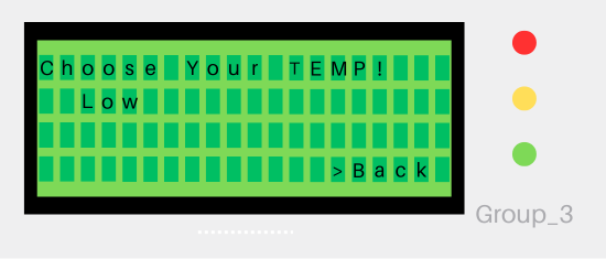
Figure 4.6 the second frame of the personalize temperature selection of automatic mode 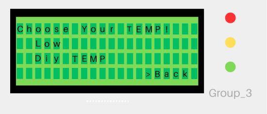
Figure 4.7 the second frame of the personalize temperature selection of manual mode - User Input Temperature (Manual)
- If the DIY TEMP is chosen, the system will bring the user into the input temperature stage, where they can input their preferred temperature based on a specific temperature range. The display is shown in Figure 4.8. To move the cursor, the user has to press the mid button, and the cursor will follow the previous setting.

Figure 4.8 user input temperature display
- If the DIY TEMP is chosen, the system will bring the user into the input temperature stage, where they can input their preferred temperature based on a specific temperature range. The display is shown in Figure 4.8. To move the cursor, the user has to press the mid button, and the cursor will follow the previous setting.
- Custom Time Input
- In the manual mode, the user is required to input their preferred duration with a maximal time of 180 minutes. The display of this stage is shown in Figure 4.9. Like the user input temperature, the user has to press the mid button, and the cursor will follow the previous setting to move the cursor. The cursor will follow the last setting.
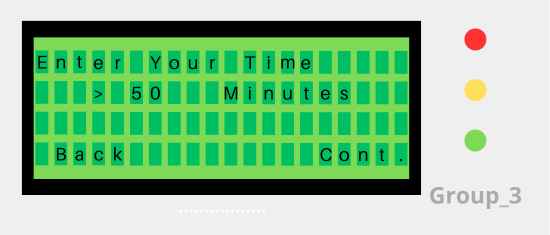
Figure 4.9 custom time input display
- In the manual mode, the user is required to input their preferred duration with a maximal time of 180 minutes. The display of this stage is shown in Figure 4.9. Like the user input temperature, the user has to press the mid button, and the cursor will follow the previous setting to move the cursor. The cursor will follow the last setting.
- User Confirmation Stage
- After all the inputted information has been successfully gathered, the next stage is the user confirmation stage, which allows the users to re-asses the inputted data. The display of this stage is shown in both 4.10 and 4.11 for the automatic and manual modes, respectively.

Figure 4.10 automatic user confirmation stage display 
Figure 4.11 manual user confirmation stage display
- After all the inputted information has been successfully gathered, the next stage is the user confirmation stage, which allows the users to re-asses the inputted data. The display of this stage is shown in both 4.10 and 4.11 for the automatic and manual modes, respectively.
- Emergency Stop
- Relating to the extra feature of the electrical sub team, the display of emergency stop is provided (see 4.12).
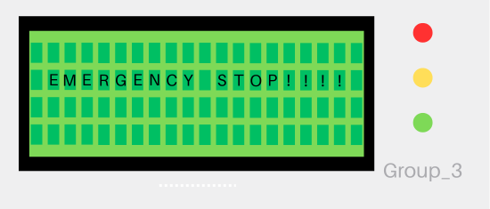
Figure 4.12 emergency stop display
- Relating to the extra feature of the electrical sub team, the display of emergency stop is provided (see 4.12).
- Processing stage
- After the user confirms to dry the clothes, the dryer will start spinning, and the LCD will show a progress display (see 4.13). As can be seen, the first two from shows the information while the third row shows the drying progress, which is demonstrated by "_" and "█". In the automatic mode, the bar shows the dryness level, while manually, it shows the time progress. In the actual LCD, the progress indicator, a bar which indicates the progress of the process, blinks. This feature intuitively allows the user to understand the progress of the dryer.
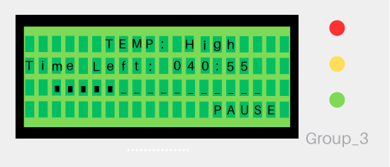
Figure 4.13 processing stage display
- After the user confirms to dry the clothes, the dryer will start spinning, and the LCD will show a progress display (see 4.13). As can be seen, the first two from shows the information while the third row shows the drying progress, which is demonstrated by "_" and "█". In the automatic mode, the bar shows the dryness level, while manually, it shows the time progress. In the actual LCD, the progress indicator, a bar which indicates the progress of the process, blinks. This feature intuitively allows the user to understand the progress of the dryer.
- Completion Stage
- After the drying has been finished, the LCD will indicate that the drying process has been compelled. The display is shown in figure 4.14
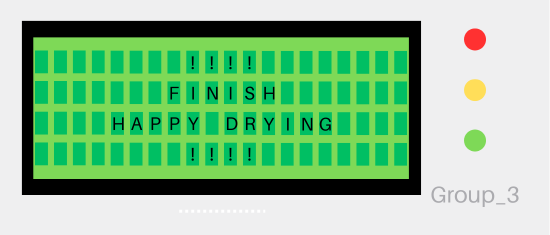
Figure 4.14 completion stage display
- After the drying has been finished, the LCD will indicate that the drying process has been compelled. The display is shown in figure 4.14
- User Input Temperature (Manual)
- In both manual and automatic modes, the user is required to input data about their temperature choice. Figures 4.5, 4.6, and 4.7 show the system's personalized temperature selection stage. As can be seen, both automatic and manual offer high, medium, and low-temperature options. By providing these options, the users are expected to have various options relating to the drying temperature considering the different fabrics' material varies in drying characteristics. In addition, in the manual mode, the user can modify their temperature in a specific range (see Figure 4.8).


Extra-feature
(1) The extra feature for the UI sub-team is providing music by involving the knowledge of physics and music to make the right pitch for the music with this mechanism:
- Using a piezo buzzer, a sound is performed by alternately sending current to the buzzer in a millisecond unit.

Figure 4.15 the physics concept behind the buzzer
- The pitches and tones are defined by implementing the right frequency and translating the period to the code function.

Figure 4.16 the function of pitch configuration
- The music "Happy birthday" is chosen as the music. The song pace and the notation were translated to the frequency and the duration, which will be saved in a separated array.
- The music sheet of happy birthday song [1]
- The music sheet of happy birthday song [1]
- Trial and error were performed to find the optimum performance of the sound, such as defining the appropriate interval.
.png)
.png)

(2) The pause manual is offered during the drying process. This feature can be used if the user decides to pause the process. This pause will stop the process while providing two different actions: back and continue. When the user press the continue option, it will continue the process with the same leftover duration or progress because this feature stores the duration that has been done before. When the user chooses the back option, it will return to the starting menu.

Structural Sub-team
Requirements
The structural team is responsible for working on various aspects of the project, including the enclosure, openings, and holes for the LCD and user interface buttons, door design, and water collection tray.
Functions
The function of the structural sub-team is to make
- an outer structure that can support the machine's internal parts, maintain rigidity, and prevent collisions that could interfere with the machine's operating performance.
- a movable structure includes; hinges and a smart locking system.
- the layout of each component as well as the connecting sections.
- a tray to use as a reservoir for condensation water.
- it easy for users to load and unload their clothes.
Objectives
The objective for the structural team includes:
- a sturdy and secure enclosure for the dryer using aluminum and appropriate screws to ensure maximum safety.
- well-positioned holes on the top layer of the enclosure to accommodate the placement of the LCD and buttons, making the dryer easy to use.
- develop a user-friendly door mechanism that prioritizes safety, allowing for easy opening and closing while incorporating features like latches and insulation to prevent accidents and maintain a secure seal.
- design a water tray with optimal dimensions and capacity to collect and manage water generated during the drying process efficiently, ensuring maximum water collection capabilities.
Constraints
The constraints for the project include:
- The dimensions of the EneRec Dryer must not exceed 250 x 220 x 300 mm. This size limitation ensures that the dryer remains within the specified space requirements
The Design
Door
We selected a round door design for the dryer, which utilizes a magnetic system with three poles for closure. After evaluating alternative arrangements, we determined that this chosen design is superior because it maximizes drying efficiency. The alternative door design was rejected based on the weight matrix analysis.
Table 5.1 Weighted Decision Matrix for Door Design Selection

Water Collection Tray
To optimize water collection in the dryer, we incorporated a standard tray design placed at the bottom of the unit. This strategic placement enhances the efficiency of water collection during the drying process. The shape of the tray was deliberately designed with a subtle circular form to maximize the surface area. This design choice ensures the tray can capture as much water as possible, further improving its collection capabilities. By utilizing a standard tray design and optimizing its shape and placement, we aimed to enhance the overall water collection performance of the dryer.
Locking System Mechanism
We opted for a magnetic door system for the dryer, employing a two-pole magnetic mechanism for securing the door. Through a comprehensive evaluation of various options, we concluded that this particular design excelled in enhancing drying efficiency. Conversely, the mechanical door lock system design was dismissed following a weight matrix analysis.
| Weight (%) | Mechanical Door Locking System | Magnetic Door Locking System | |
|---|---|---|---|
| Design |  |
 | |
| Durability | 50 | 3 | 2 |
| User Friendly | 30 | 1 | 4 |
| Compact | 20 | 1 | 4 |
| Overall | 100 | 2 | 3 |
Conclusion
The final product of our project is a prototype of an energy recovery dryer, which has lower energy consumption than conventional dryers. Considering the energy efficiency policies in 2022/23 – 2024/25 Service Plan by BC Ministry of Energy, Mines and Low Carbon Innovation, our dryer can be a viable option for transitioning to sustainable products. Since dryers are essential household appliances, switching from conventional dryers to energy recovery dryers is expected to contribute to environmental improvements, such as reducing greenhouse gas emissions.
Enerec prototype is user-friendly and relies on three buttons to receive temperature and time inputs from the user in manual mode. In addition, an automatic option is also available, ensuring effective drying. Enerec is also equipped with a door lock detector and a magnet lock system, making it safe even for children. The round transparent door design allows users to see inside without opening the door. The Enerec's heat exchanger comprises copper tubes that condense water and recycle heat back into the system instead of venting it out, resulting in less energy waste than conventional dryers. Along with the baffles in the drum load, which are driven by gears, the dryer functions effectively in drying clothes and is suitable for everyday household use.
Appendices
Team Gantt Chart
Pdf Drawings
- Assembly Drawing
File:Exploded View Assembly Team 3 pdf.pdf
- Mechanical PDF Drawing https://drive.google.com/drive/folders/1xj4SfBFHjn_vYT0kC4ie8MTgaUiOV3x_?usp=drive_link
- Electrical PDF Drawing https://drive.google.com/drive/folders/1awsvvdSdAMV1rLdagIpWwO3z_lmj7svu?usp=sharing
- Structural PDF Drawing https://drive.google.com/drive/folders/1cN8_rShuCR_-Ws4K2H5-rdZrsdXnyx4c?usp=drive_link
Arduino Code
Photorealistic Render
 |
 |
Sustainability Report
References
Chay, C. (2022). Free CAD designs, Files & 3D models: The grabcad community library. Free CAD Designs, Files & 3D Models | The GrabCAD Community Library. https://grabcad.com/library/3d-arduino-uno-r3-1
López, E. M. (2022, February 28). happy birthday[recorder notes]. Recorder Notes. https://www.recordernotes.org/songs/happy-birthday-recorder/
Pimenta, W. (2023). Free CAD designs, Files & 3D models: The grabcad community library. Free CAD Designs, Files & 3D Models | The GrabCAD Community Library. https://grabcad.com/library/metaltex-av16-er2-o16mm-1
Shlomi, D. (2022). Free CAD designs, Files & 3D models: The grabcad community library. Free CAD Designs, Files & 3D Models | The GrabCAD Community Library. https://grabcad.com/library/breadboard-23
SPEIM. (2021). Free CAD designs, Files & 3D models: The grabcad community library. Free CAD Designs, Files & 3D Models | The GrabCAD Community Library. https://grabcad.com/library/lcd-20x4-2
ENEREC Demonstration Video:
About Us
| Documentation Sub-team | |||
|---|---|---|---|
 |
Debora Serlitia
Documentation Sub-team Member
|
 |
Saraswati Dasi
Documentation Sub-team Member
|
| Mechanical Sub-team | |||
 |
Aprisa Putri Gunawan
Mechanical Sub-team Member
|
 |
Jerry Pasaribu
Mechanical Sub-team Member
|
| Electrical Sub-team | |||
 |
Yuanzhe Wangzhang
Electrical Sub-team Member
|
 |
Nuri Ertan
Electrical Sub-team Member
|
| User Interface Sub-team | |||
 |
Charisma Rusdiyanto
User Interface Sub-team Member/ Team Leader
|
 |
Sinta Cecilia Ambarita
User Interface Sub-team Member
|
| Structural Sub-team | |||
 |
Ali Akbar Alaydrus
Structural Sub-team Member
|
 |
Yusuf Ananda Lution
Structural Sub-team Member
|
Contact Us
We will be delighted to address further questions about our project. Please feel free to contact us by email for any business inquiries.
| Concern | Contact Person 1 | Contact Person 2 |
|---|---|---|
| Documentation Issues | serlitia@student.ubc.ca | ndasi01@student.ubc.ca |
| Mechanical Issues | aprisa11@student.ubc.ca | jpasarib@student.ubc.ca |
| Electrical Issues | ywangzha@student.ubc.ca | nertan@student.ubc.ca |
| User Interface Issues | crusdiya@student.ubc.ca | sambarit@student.ubc.ca |
| Structural Issues | aallii@student.ubc.ca | ylution@student.ubc.ca |