Course:VANT151/2022/Capstone/APSC/Team5
Home
Team 5 Project: Energy Recovery Clothes Dryer
Welcome to Team 5's Wiki page of EneRec Dryer Project. The project is a part of UBC Vantage College course VANT 151 (2021-2022), which is directed by Dr. Ernest Goh. This Wiki Page aims to report team 5's progression of the clothes dryer design and our final product.
Thanks for all the group members and their contributions to this project.
Project Overview
Problem Statements
The issue of the dryers designing is that the current dryers have huge energy consumption by heating the air for a long time but using the hot air once only.
Objectives
Objectives of this project are:
- Higher efficiency of the drying process.
- Lower energy loss during the drying process.
- Efficient energy recovery.
- User friendly.
- Sustainable drying process.
Functions
Basic functions of the clothes dryer are listed below:
- Five buttons are used to control the panel. User can use them to select the option in the interface.
- User can choose the time and temperature they want.
- The LCD can show the remaining time when the dryer is working.
- User can select pause to let the dryer stop working.
Constrains
Necessary requirements for this project that must be satisfied:
- Size limitation of 250 x 220 x 300 mm with at least 0.5 L capacity.
- Ability of drying a cotton handkerchief with 15 x 15 cm size in 1 hour.
- Maximum allowable electrical power consumption of 24 V AC, 40 VA.
- Useable automatic operating mode.
- Desired setting of drying time, temperature and dryness.
- 8 Weeks for the entire design.
Working Distribution
Team 5 has 10 members and divided into 5 sub-teams. The following part aims to show the working assignment of each sub-teams.
- Documentation: Gantt chart, website, slides, render, sustainability.
- Electrical: Motor & fan, heater, sensor, EE program.
- Mechanical (& Thermal): Drum drive, 3DP parts, sensor mount, heat exchanger, seals/insulation.
- Structural: Enclosure, openings/holes, door & latch, tray.
- User-Interface: operating program, UI program, LCD, input hardware.
Gantt Chart
Table 1 below shows the schedule of all the sub-teams' tasks and their beginning and ending dates.

User-interface Design
Requirements
The user-interface subteam works on the operation of the program, user-interface interaction, LCD and button connections.
The operation of the EnerRec Dryer includes selecting the drying mode and drying time.
The user-interface program receives input from the buttons and displays output on the LCD screen.
Objectives
The objective of user-interface subteam is designing a program that allows users to control the operation of the dryer. The elements of the interface includes LCD, five buttons, etc.. Users can see the remaining time of drying on the LCD, and they are able to use use the buttons to select the options in the interface, choose the time and temperature they want, and pause the dryer.
Functions
The user-interface allows users to choose the drying time and drying mode with the buttons, and the LCD screen allows an easier way for users to read the information of the dryer and displays functions in a user-friendly way.
Constraints
1.There is at most 5 buttons available.
2.The size of the LCD screen is 20x4, it can not show long characters.
3.The drying temperature is constrained by the heater.
Limitations
1.The menu page can not show the all three modes (normal, heavy duty, delicates) at the same page.
2. Users can not choose the drying time and temperature, which are defined in the modes.
3. Users can not pause during the drying process.
The Design
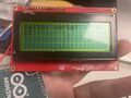
LCD screen Demo

Hardware Layout

1.Buttons
For the button layout, initially we chose to use five buttons for the fully control of the mode, time and temperature. The middle button for "OK", and the surrounding buttons each for "Up", "Down", "Left" and "Right". After coding and brainstorming other page layouts, we found that we could simplify the buttons and use only three of them: Left, Right, OK.
The second design has some advantages compared to the initial one:
- The wire connection is simplified
- The control of the dryer becomes easier for users
- The programming of the codes becomes much easier
However, there are also some drawbacks:
- Users can not view the whole options on the same page
- There are less options in modes
2. Main Menu Page
There are four options on the main menu page:
- Normal
- Heavy Duty
- Delicates
- Return
Normal Mode has the preset of 55 degrees Celsius and 41 minutes dry time. We referred to LG's dryer while setting the drying time.
Heavy Duty has the preset of 60 degrees Celsius and 54 minutes dry time.
Delicates has the preset of 50 degrees Celsius and 28 minutes dry time.

Program Flowchart

Mechanical Design
Requirements
The mechanical sub-team is supposed to generate, design, and create the mechanical components of the Dryer Machine, following the guidelines and the constraints.
The group is responsible for designing and creating a drum drive, some 3D printing components including mount and support for sensor and motor, computer-aided designs for electrical parts and a heat exchanger.
Objectives
- Maximize the effectiveness of the mechanical parts.
- Minimize the possibility of problems.
- Make the solution of the problems as convenient as possible.
Functions
- The fan and the heat exchanger must work smoothly when drying cloth.
- The mechanic system can affect the storage and make the cloth inside dry faster.
Constraints
- Minimum capacity of 0.5L, able to dry a cotton handkerchief, size 15 x 15 cm (± 3 cm) within 1 hour.
- Components must be in side of the structure of the dryer, which cannot exceeding 250 x 220 x 300 mm.

Drum Drive Mechanism Design Alternatives
Drum drier is mainly compose of drum itself and a motor that drives it. The function of drum is to storage the laundry that need to be dried. The motor provides power for the rotation of the drum. In addition, a complete drive system is required to connect the motor and the drum. The figure 1 shows the design idea of thermal cycle and the belt drive systems. Figure 2 shows the design of motor support and figure 3 is the feasible idea that let sensor mount in the drum.

Evaluation
| Idea | Disadvantages | Advantages |
|---|---|---|
| 1 |
|
|
| 2 |
|
|
| 3 |
|
|

The table shows the advantages of belt drives over gear drives. It is more durable, easier to maintain, and has less mechanical energy loss. Although the energy loss of the belt cannot be completely avoided, and it is impossible to repair it without a professional, it has already improved compare with gear drive system. In addition, the belt drive is lower in noise than the gear drive in actual use. This factor is also why we chose it.This is the reason why we choose belt drive system in the end.
Basic Features

Components
- Drum drive comoponents
- Motor Support
- Pulley
- Sensor Mount
- 3D Printing Parts
1.Drum drive comoponents
The dryer adopts belt drive system to provide power for the rotation of the drum. As shown in Figure 1, in this system, a large pulley is connected to the drum, the small pulley is connected to the motor, and the belt is wound in the middle of the groove of the pulley. The two pulleys will maintain a certain distance to avoid friction between the pulleys. At the same time, increasing the tension of the belt in this system make the operation noise less and the service life longer.
2.Motor Support

The function of the motor bracket is to fix the motor and ensure the stability of the transmission system. It is a 3D printed three-dimensional tripod and the motor is fixed by the screw brackets on both sides. The advantage of this design is that the motor height can be adjusted freely and the stability of the tripod is better. In addition, the hollow tripod saves material and printing time.
3.Pulley
The two rollers are designed with corresponding grooves according to the width of the belt. The purpose is to ensure the stability of the belt drive. The two rollers are one large and one small, in order to save space and exert the kinetic energy of the motor more efficiently.

4.Sensor Mount
To prevent danger, the sensor mount is placed inside the drum. The placement of the sensor mount is designed at the lower left of the drum panel. This has two main advantages. On the one hand, make the sensor mount cable close to the circuit board to facilitate circuit layout. On the one hand, the sensor position is relatively far away from the thermal circulation system to measure the humidity and heat in the barrel more accurately.
5.3D Printing Parts
The drum panel, rollers, motor bracket and heat exchange system housing in this dryer are all 3D printed parts.
Electrical Design
Overview of the electrical and electronic sub-system
The Electronics and Electrical Team (EE Team) is responsible for all electronic circuits including but not limited to motors, fans, heaters, power supplies and sensors. It also manages the Ene Rec system in automatic and manual modes of the program. This connection can be seen in Figure 7.

Main component list
Table 2. Component list of the dryer
| Component | Specification |
| Motor | Hobby Gearmotor, Yellow 200 RPM, 3-6VDC |
| Fan | 12 VDC motor |
| Heater | 33 Ohms 7W resistor |
| Temperature and Humidity Sensor | DHT11, 5V |
| Microcontroller | Arduino Uno R3 ATMEGA328 |
Requirements
Functions
- The circuit can provide enough power and enough heat to dry clothes.
- Includes automatic mode for drying laundry.
- Change the temperature inside the drum according to user settings.
- Use the motor to continuously rotate the drum in different directions.
- Track temperature and humidity inside the dryer with the sensor.
- Use the motor to continuously rotate the drum in different directions.
- Set manual mode according to drying time, temperature, and degree of drying.
- The electronic circuit of the dryer must be safe for the user.
- The motor, heater, and fan should be able to work at the same time.
The Design
Objectives
- Make sure the circuit of the dryer should be safe and efficient.
- Shorten drying time.
- Make sure the clothes are not overheated to avoid damage to the clothes.
- Ensure the design is cost-effective
Constraints
- The maximum power voltage is 24AC and 40VA.
- All parts need to go in the dryer and each part should operate simultaneously.
Power Supply
Arduino Uno needs about 9V for powering. The normal voltage is 12V. In order to drop the voltage from 12V to 9V, a voltage regulator and capacitors are needed. A bridge rectifier circuit can complete the conversion, as can be seen in Figure 8.
.png)
Fan Circuit
The power of the fan circuit is a 9VDC. Fan circuit includes several parts: MOSFET (Q1), capacitor (C5, 0.1 u, > 50V), fan, resistor (R2, 10k),and diode (D1, 1A, 50ns). This fan circuit keeps the fan under 50%duty cycle.
The fan circuit schematic is in Figure 9.

Drum Motor Circuit
The drum motor using +5V voltage. The Drum Motor circuit includes: resistor (R3), diode (D1), Drum motor, capacitor (C6, C10), and MOSFET (Q1). MOSFET enables the motor to start slowly. Motor will be first started and lest ended. The motor circuit schematic of the drum motor is in figure 10.

Heater Circuit
The heater uses 12V voltage supplied from breadboard. The Heater circuit contains: heater, capacitor (C7:10n), resistor (R1:10k, R6: 39, R7: 270, R8:150), LED2, and Triac (T1: 4A, 600V). Heater will be last started and ended first. Air will flow from fan below to heater. The circuit schematic of the heater can be seen in figure 11.

Temperature and Humidity Sensor
In the temperature control circuit, when the temperature rising reach the highest temperature of the sensor, the circuit cut of to stop heater working. Shown in Figure 12.

Structural Design
Requirements
The structure group is responsible for the structural assemble of the whole box, including the design of frame, door, latch, UI components and holes on the box. The housing includes all the designs mentioned above, and all the parts are combined to make a dryer.
Objectives
Our design goal is to make a dryer shell, including the door opening, water inlet pipe and some buttons for operation. At the same time, our design should also meet the ergonomic convenience.
- The cloth dryer is supposed to be used by all ages people.
- The opening door should be safe enough to be used.
- The function of the LCD screen and the buttons should be easy to be used by the user.
Functions
The functions of the S-sub team are designing the whole structure of the dryer
- The door should be prevent the clothes from getting out from the dryer.
- The LCD screen and buttons can be easily seen and used.
- The water collection tray is needed as collecting the water when the dryer is working.
Constraints
All parts and shells are limited by the size of materials. The shell will need to design an optimal scheme according to the size of materials provided. The size of components is determined according to the final shell size.
- The dryer is not easy to be carried.
- The dryer can't be too expensive
- The dryer can't operating with a very high temperature (because of the heat resistance of the material).
- The dryer need to have a bigger screen to give more instructions to the user about how to use the dryer (more guidance).
Design
Enclosure
In the front view, there is a door. The door is fixed on the front panel. There is a square hole in the middle of the panel. It is designed to be square because it can reduce the probability of clothes falling out of the drum to a certain extent. The side view shows the design of the side panel. In the lower right corner, there is a hole that can take out the water collection tray, so that the water collection tray can be taken out and poured out after it is full of water. In the view at the back, we use the iron plate as the construction material. There are holes on the iron plate for the heat dissipation pipe and nail holes for fixing the internal parts. The view at the top shows that the panel at the top has square openings for installing LCD screens, and there is also space for installing control panels for user operation. The positions of all holes and nails have been measured according to the installation method of internal parts, so as to ensure that there will be no installation failure during installation.


Door
Our original intention in designing the door is that the door can completely cover the opening. As for the shape of the door, we have had several alternatives before, such as designing it into a square or a circle. Finally, we chose the square door. The first reason is that the square door can fit the design shape of the panel. The second reason is that the square door is designed to be more convenient to design the connection hole between the door and the panel. Therefore, the square door is better installed and more stable, and it is also more concise and beautiful in appearance. The size of the door is 150mm * 150 mm.


Water Collection Tray Panel Design
We designed the size of the hole on the side panel to be 39mm * 29mm. This size well conforms to the size of the water collection tray made by the mechanical team. The design of this hole allows the collector to be placed and pulled out freely. At the same time, it can ensure that the collector will not fall off from the internal structure. This design not only ensures the stability, but also gives users the greatest degree of convenience.

User interface CAD
According to the LCD screen selected by u sub team and the control panel for users, we have made corresponding punching design on the top panel. The rectangle shown in the same figure is used to place the LCD screen, with a size of 87mm*42mm. Holes designed for buttons on the control board are also designed nearby. The control panel and LCD screen are designed at the top for the convenience of users. This design will be more convenient for users to operate and observe the display on the screen.


Final Product
The final product of our designed dryer is shown in the following pictures:
Overview:
Front view:
Left view:

Right view:
Back view:

Bottom view:

Conclusion
Our final product is a dryer that can recycle heat repeatedly. The design of 6 copper tubes is used to condense the water and repeatedly transport the heat back into the system. Therefore, compared to the traditional way the dryer vents the excess heat, our designed dryer saves more energy. The 5 buttons are designed for easier humidity and temperature adjustment, allowing users to understand how to operate in a simple way. In addition, the small size dryer is more portable and space-saving. Therefore, the dryer we designed is a good choice.
Appendices
PDF Drawings
The figure 13 briefly shows the layout of the dryer. The flowchart of the program is also shown in below.


Arduino Code
#define heater 8
#define fan 9
#define motor 10
void setup() {
pinMode(8, OUTPUT);
pinMode(9, OUTPUT);
pinMode(10, OUTPUT);
}
void loop() {
for (int fadeValue = 0 ; fadeValue <= 255; fadeValue += 5) {
analogWrite(fan, fadeValue);
delay(30);
}
for (int fadeValue = 0 ; fadeValue <= 255; fadeValue += 5) {
analogWrite(motor, fadeValue);
delay(30);
}
digitalWrite(heater, HIGH);
delay(5000);
digitalWrite(heater, LOW);
for (int fadeValue = 255 ; fadeValue >= 0; fadeValue -= 5) {
analogWrite(motor, fadeValue);
delay(30);
}
for (int fadeValue = 255 ; fadeValue >= 0; fadeValue -= 5) {
analogWrite(fan, fadeValue);
delay(30);
}
delay(5000);
}
UI Code
#include<LiquidCrystal.h>
#include<LiquidCrystal_I2C.h>
#include<OneWire.h>
#include<DallasTemperature.h>
#include<DHT.h>
#define DHTPIN 10
#define DHTTYPE DHT22
DHT dht(DHTPIN, DHTTYPE);
const uint8_t PinLcdCLK_ui8c=A5;//CLK
const uint8_t PinLcdDAT_ui8c=A4;//DAT
LiquidCrystal_I2C lcd(0x27, 20,4);
//*********MODE**********MODE**********MODE************MODE********MODE*******MODE****
bool normalMode;
bool heavyDutyMode;
bool delicatesMode;
int count;
int startTime;
int currentTime;
long int timeDuration;
long int normalTime=2460000;
long int heavyDutyTime=3240000;
long int delicatesTime=1680000;
//*********HEATER**************FAN***************MOTOR**********SENSOR****************
const int fanPin=7;
const int heaterPin=8;
const int motorPin=9;
int tempThreshold;
const int tempThresholdN=55;//the temperature that the heater needs to reach
const int tempThresholdHD=60;
const int tempThresholdD=50;
float temperature;
float humidity;
OneWire oneWire(DHTPIN); // setup a oneWire instance
DallasTemperature sensors(&oneWire); // pass oneWire to DallasTemperature library
//********BUTTON************BUTTON************BUTTON**********************************
const int bPinUp=2;
const int bPinDown=3;
const int bPinLeft=4;
const int bPinRight=5;
const int bPinOK=6;
//button pin numbers
int bStateUp=0;
int bStateDown=0;
int bStateLeft=0;
int bStateRight=0;
int bStateOK=0;
//button state
//*****SETUP**********SETUP***********SETUP***********SETUP*************************
void setup() {
pinMode(PinLcdCLK_ui8c,OUTPUT);
pinMode(PinLcdDAT_ui8c,OUTPUT);
lcd.init();
lcd.backlight();
lcd.clear();
lcd.begin(20,4);
//init lcd using lcd.begin(numCols,numRows);
Serial.begin(9600);
//*********HEATER**************FAN***************HEATER**********FAN****************
pinMode(fanPin,OUTPUT);
pinMode(heaterPin,OUTPUT);
dht.begin();
//*****BUTTON*********BUTTON**********BUTTON**********BUTTON************************
pinMode(bPinUp,INPUT_PULLUP);
pinMode(bPinDown,INPUT_PULLUP);
pinMode(bPinLeft,INPUT_PULLUP);
pinMode(bPinRight,INPUT_PULLUP);
pinMode(bPinOK,INPUT_PULLUP);
//initialize pushbutton pin as input
}
//*****LOOP************LOOP*************LOOP****************LOOP********************
void loop() {
lcd.setCursor(0,0);
//set the cursor to column 0, line 0
//******BUTTON**********BUTTON**********BUTTON**********BUTTON**********************
bStateUp=digitalRead(bPinUp);
bStateDown=digitalRead(bPinDown);
bStateLeft=digitalRead(bPinLeft);
bStateRight=digitalRead(bPinRight);
bStateOK=digitalRead(bPinOK);
WelcomePage();
}
//******FUNCTION*********FUNCTION***********FUNCTION***************FUNCTION********
void WelcomePage(){
lcd.clear();
lcd.setCursor(0, 0);
lcd.println("Hello!Thank You for");
lcd.println("Using Our Dryer!");
lcd.setCursor(0,3);
lcd.print("Press OK to continue");
if(bStateOK==0){
Normal();
}
}
void EndPage(){
lcd.clear();
lcd.setCursor(0,1);
lcd.println("Thank you for using");
lcd.println("our clothes dryer");
}
void Normal(){
lcd.clear();
lcd.setCursor(0,0);
lcd.print("Time:41 minutes");
lcd.setCursor(0,1);
lcd.print("Medium temperature: 55 degrees Celcius");
lcd.setCursor(0,2);
lcd.print("Start:Press OK");
lcd.setCursor(0,3);
lcd.print("Press right to Heavy Duty");
if(bStateOK==0){
normalMode==true;
Start();
}else if(bStateRight==0){
HeavyDuty();
}
}
void HeavyDuty(){
lcd.clear();
lcd.setCursor(0,0);
lcd.print("Time:54 minutes");
lcd.setCursor(0,1);
lcd.print("High temperature: 60 degrees Celcius");
lcd.setCursor(0,2);
lcd.print("Start:Press OK");
lcd.setCursor(0,3);
lcd.print("Press right to Delicates");
if(bStateOK==0){
heavyDutyMode==true;
Start();
}else if(bStateRight==0){
Delicates();
}
}
void Delicates(){
lcd.clear();
lcd.setCursor(0,0);
lcd.print("Time:28 minutes");
lcd.setCursor(0,1);
lcd.print("Low temperature: 50 degrees Celcius");
lcd.setCursor(0,2);
lcd.print("Start:Press OK");
lcd.setCursor(0,3);
lcd.print("Press right to Normal");
if(bStateOK==0){
delicatesMode==true;
Start();
}else if(bStateRight==0){
Normal();
}
}
void Start(){
lcd.clear();
lcd.setCursor(0,0);
if(normalMode==true){
tempThreshold=tempThresholdN;
timeDuration=normalTime;
}else if(heavyDutyMode==true){
tempThreshold=tempThresholdHD;
timeDuration=heavyDutyTime;
}else if(delicatesMode==true){
tempThreshold=tempThresholdD;
timeDuration=delicatesTime;
}
startTime=millis();
for(count=timeDuration;count>=0;count-=millis()){
currentTime=millis();
count=(timeDuration-currentTime)/60000;
lcd.print("Time: ");
lcd.print(count);
lcd.print("min");
lcd.setCursor(0,1);
lcd.print("Temperature: ");
lcd.print(temperature);
lcd.print("C");
lcd.setCursor(0,2);
lcd.print("Humidity:");
lcd.print(humidity);
temperature = dht.readTemperature();
humidity=dht.readHumidity();
if (isnan(humidity) || isnan(temperature)) {
Serial.println(F("Failed to read from DHT sensor!"));
return;
}
if(temperature > tempThreshold) {
Serial.println("The heating element is turned off");
digitalWrite(fanPin,HIGH);
digitalWrite(heaterPin, LOW); // turn off
digitalWrite(motorPin,LOW);
} else if(temperature < tempThreshold){
Serial.println("The heating element is turned on");
digitalWrite(fanPin,LOW);
digitalWrite(heaterPin, HIGH); // turn on
digitalWrite(motorPin,HIGH);
}
}
digitalWrite(fanPin,LOW);
digitalWrite(heaterPin,LOW);
digitalWrite(motorPin,LOW);
EndPage();
}
Renderings and photo view 360
The following pictures shows the final result with renderings:
References
The circuit:- gate of MOSFET attached from digital pin 9 to ground.
created 1 Nov 2008
by David A. Mellis
modified 30 Aug 2011
by Tom Igoe
modified 2019
by Ernest Gohre.
About us
| Structure | |
|---|---|
| Thompson Ma (Team Leader)
mhs2002@student.ubc.ca from Xi'an, Shaanxi, China Interest: basketball, NBA, Warriors, Polls |
Wenyu Tang
twy0329@student.ubc.ca Wuxi, Jiangsu, China Interst: Novels |
| Electrical | |
| Tianhao Zhang
Zhang1207th@163.com From China |
Yiming Pan
panyiming0516@163.com China |
| User-Interface | |
| Allison Jiao
allis0n@student.ubc.ca Nanjing, Jiangsu, China Interest: Dortmund F.C. |
Zhehao Liu
zhao618@student.ubc.ca Wenzhou,Zhejiang,China Interest:Movies |
| Mechanical | |
| Jingxuan Chen
ww66692@student.ubc.ca Beijing, China interest: bioengineering, history, political economy |
Tianchen Yuan
yuantc20@student.ubc.ca Jiangsu, Suzhou,China |
| Documentation | |
| Wenxiang Ning
wxiang03@student.ubc.ca Chinese, from Kunming, Yunnan, China. Interest: Cat petting. |
Jingwei Zhang
zjw2003@student.ubc.ca Beijing, China |


