Course:VANT151/2021/Capstone/APSC/Team4
Home
Project: Energy Recovery Clothes Dryer
Team 4 is an engineering team for the creation of energy recovery clothes dryer to dry wet clothes less than 1 hour. The dryer is being designed to dry wet objects with minmum energy cost towards sustainable technology.
Project Overview
Problem Statement

The users stated standard dryer consumes large electrical energy and takes long time to dry wet clothes.
Project Objective/Goal
For VANT 151 project, team 4 designed and created a scaled energy recovery clothes dryer prototype within 8 weeks using solidworks, tinkercad and physical components.
Photorealistic Dryer Model and Assembly Drawing
Figure 1 shows the design prototype as a photorealistic model. The pdf file indicates the assembly drawing of entire dryer.
Team Information:
The whole group consists 12 members, and divided into 6 sub-teams. The responsibility for each team is shown below:
Documentation: Drafting the wiki page and writing the final wiki, creating the Gantt Chart and also contribution to the basic features of the project.

User-Interface: Operation program, user-interface program, LCD connections, buttons connections.
Mechanical: Drum drive, 3D printed parts (designing and modifying), animation of drive mechanism, CAD files of EE parts.
Electrical: Electrical circuit, heater and programming.
Structure: The enclosure, various opening and holes, door and latch, animation of door or other means of access, CAD files of UI parts.
Thermal: Standard design of heat exchanger cover, standard design of water collection tray, seals and insulation, flow simulation and animation of air flow.
Table 1 shows the schedule for each team's tasks working period with beginning dates and end dates.
User-Interface Design
Requirements

Functions
- Default start
- Adjust operate temperature and time
- Safe insurances: Emergency stop, Safe lock and Open door protection
- LCD brightness setup
- Entertainment: Game
Objectives
- Entertainment functions could be provided for users while they are waiting for the operation.
- The LCD provides adequate information for users so that they do not need a specification to learn to use.
- The Arduino should be able to process the input commands (e.g. users press the buttons) correctly, without the situations that buttons were pressed once and responded twice.
Constraints
- The users' experience must be the first consideration.
- The dryer must be safe during operation.
- The system have to be stable, no bugs were allowed.
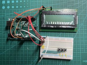
Figure 3. 3 buttons layout of hardware

The Design
Hardware Layout
To design the UI system, two type of hardware layouts was considered. The first type is a 5 buttons layout (Figure 2). The function of buttons are up, down, left, right and OK respectively. This is a standard layout with no limitations in the functionality. However, due to the size of the LCD screen, button "up" and "down" might become redundant in both the system designing and user interacting. Thus, a 3-button-layout was developed (Figure 3). The buttons' up and down were abandoned to simplify the UI system. Nevertheless, some entertaining features might have to be deleted due to this change.
After the discussion of Team 4, the 5 buttons layout was finally decided. The advantage of this layout is that i could simplify the manipulation of users, as well as could be easier to learn to use the system.
Additional Features
Sensors
A temperature and Humid sensor was added to monitor the condition inside of the dryer. When the temperature is higher than the set temperature, the heater will stop function. In the auto mode, the dryer stops working when the humidity reaches 20%.
Open Door Protection
Two limit switches were added to ensure safety. One of the switches is used to detect the door condition. If the door is opened during operation, the system will pause the operation.
Emergency Stop
The other limit switch is a emergency stop, which could always interrupt the system, and return to the main menu. This function is to ensure the safety of the dryer. If any emergency sitautions happened, the emergency stop function is the last guarantee.
Entertainment
A game could be accessed before or after the dryer is functioning. The user could play the game to kill time while they are waiting for the clothes to dry.
Safe Lock
Whether the dryer is working or not, safe lock could be opened to disable all the buttons (except emergency stop). This function is developed to prevent kids or pets from mistake operations. To unlock, as well to avoid unintended unlock, five buttons must be pressed at the same time.

UI Structure Design
In the main menu, five items were included, which are Start, Temperature, Time, Game, and Option (Figure 4). Due to the size of the LCD, the items could not be included in one screen, so this menu was designed to be scrollable. In the Temperature and Time submenus, operation time and temperature could be set. The user could also press Start directly and leave the setups in default values. In the Options submenu, the brightness of LCD could be set, and safe lock could be opened. After the operation is started, the user could still access games or open safe lock, as well as stop the operation before finishing. If the door of the drier is opened, the operation will be paused. Whenever the emergency stop button is pressed, the drier will always stop functioning and lock up.

UI System Flowchart
Figure 5 is the flowchart of the UI system. Since the structure of this program is not linear, the tasks of the program could be executed at the same time, and could always back to the previous menu. Thus, the flowchart is mostly horizontal.
UI System Program
The full program is attached below.
.jpg)
Documentation:VANT151/2021/Capstone/APSC/Team4/Sub-Team UI/UI System Program
Reccomendations
- To improve the UI system, the algorithm could be optimized. The global variables takes too much memory of the Arduino. For example, some of the boolean varaibles might be combined, and more byte type variable could be used instead of int.
- For some of the screen displays, there is no need to erase and print the whole display. Instead, the method in the "game" function could be applied, that is, only the select symbols were erased and renewed to respond the buttons. This way, some Arduino storage could be saved. However, the disadvantage is also obvious, that the select symbols might blink, which makes the user uncomfortable.
Mechanical Design
Requirements
Functions
- The sensors can detect the temperature and humidity of object.
- The clothes should be dried evenly by rotating the drum in the dryer.
- Drum is able to rotate in different speed.
- Drum stops rotating when object is below certain humidity.

Objectives
- Stable and quite drying process.
- Minimize energy cost
- Effective drum rotation
- Maximize dryer's lifespan
- Rotate in different speed
Constraints
- Dryer volume can not exceed 250mm x 220 mm x 300 mm
- Dryer should be able to dry a 150 x 150 mm cotton handkerchief within 1 hour.
- Dryer must contain least 0.5L capacity
- The sensor mount should fit the sensor design
- The motor support must hold the motor and the bottom must be stabilized
The Design

Drum Size
Inner shell: The diameter of the drum is 100mm, height: 100mm; Outer shell (rings): The diameter of the drum is 104.2mm, height: 100mm; The thickness of the white ring shell is 4.2mm; The diameter of the half-cylinder (bulge) is 4.2mm, height: 20mm. According to the capacity equation: V=(L)(Pi)(R^2)-2(pi)(r^2)(l), the volume of the drum is approximately 0.78L.
Drum Evaluation/Compare and Contrast between Alterative Design and Final Design
The figure 6 and 10 show design 1, 2 and 4 are using belt to rotate drum whereas the drum is rotated by gear in design 3. In design 1, the pulley is on one side of the motor and only one belt is used to drive the drum which has relatively low efficiency. The difference between design 2 and 1 is design 2 contains 2 belts. Therefore, the drum in design 2 can be rotated easily and the efficiency than the design 1. However, because two pulleys are on one side of the motor, lots of centrifugal forces are produced when the pulleys are spinning in high speed, and the motor support may collapse.

Design 3 is different with other alternatives design because it uses gears to drive. The advantage of this design is that the drum rotates easily as the motor starts to spin. However, it makes a lot of noise as the motor is working. In addition, the heat dissipation of two spur gears wastes massive energy. Lastly, the design 4 is the best design since it is similar to the design 2, but the motor is balanced as two pulleys are set on both sides of it.
Drive mechanism
Drum is powered by direct current to remain rotation in one direction. When motor is powered, it initiates two pulley that are connected with belts to rotate drum drive.
Motor Support

The outer ring and inner ring of motor are respectively 18.8mm x 22.5mm and 16.3mm x 20mm. With the combination of two hollow cube of this particular sizes, the upper part of motor support that stabilizes motor is obtained. Besides, with the support of four pillars and a bottom plate with the dimension of 50mm x 50mm, the motor support can be fixed on the ground steadily.
Temperature and Humidity Sensor
Two sensor were placed far from the drum and heat to prevent collapse from rotation and high temperature. The top part of the sensor support was attached to the top panel with two nuts.
EE Parts CAD
The EE components' CAD files are shown in the merged figure below.


Animation of the rotation drum
Recommendation
- To improve the stability of the drum drive, add one more drum support on each side to make a triangle shape instead of putting the support right under the drum, and stable the support on the button of the dryer with a screw.
Electrical Design
Requirements
Functions
- Users can set different drying modes (e.g., fast drying mode, power-saving mode, etc.), working hours or dryness of clothes, and the drum dryer will operate according to the user's input instructions.
- The dryer can obtain data through the temperature and humidity sensor in the drum, and realize the automatic adjustment of the temperature in the working area (inside the drum).
- When the dryer is working, the dryer door is locked. Only by clicking the stop button to stop the dryer can the hatch be opened.
Objectives
- Connecting the Fan, Drum Motor, Heater and Temperature/Humidity Sensor in a circuit.
- The Fan, Motor and Heater can be controlled by program in Arduino and connected with user interface.
Constraints
- The code of Arduino program should be concise and clear.
- Follow the rule of low cost and less number circuit components and avoid crossing wires.
- Using appropriate resistor and capacitor to stabilize current and protect circuit to prevent the excessive current causes electronic components to burn out.
Arduino
What is Arduino?
Arduino is an open-source electronics platform based on easy-to-use hardware and software. It is the easiest and fastest way to build a simple program to implement simple instructions. The instructions of arduino are based on the Arduino programming language and the execution of the instructions is carried out by some adapted hardware. The basic operating principle of arduino is to write a specific code into the CPU of Arduino by a computer and this function will be executed by a assembly circuit. Generally, this circuit is base on the structure of breadboard, which is easy to assemble. In this project, the operating of circuit is based on the Arduino system. We assembled the fan, motor, heater and temperature sensor together in the circuit of dryer and wrote the code to control the operation of these components.
Design Evaluation
Table 2. Comparing the alternative design
| Design | Cost | Drying efficiency | Ease of implementation | |
| Rotating Direction | Single | Low | Low | Easy |
| Double | High | High | Difficult | |
| Position of Sensor | Connecting with fan and heater | High | Low | Difficult |
| Connecting with heater | Low | High | Easy | |
Table 2. above compares the several design options. The rotating of the motor can be controlled by the Arduino program, and there are two possible rotation directions. One is one-way rotation(single direction), and the other is two-way alternate rotation (double direction). The production costs of both switches are the same. But the two-directional operation would cause relatively large damage to the parts, so the future maintenance costs might be higher than single direction rotation. The unidirectional rotation design uses less power than the directional rotating and small damage to the motor, so the electricity bill will be less. The dryer drum is also easier to install in one direction. However, the one-directional operation is less efficient than the two-directional operation and takes more time to dry. Finally, a single direction was chosen and installed in the drum.
The humidity and temperature sensor could be connected in series with the heater and fan, or only connected in series with the heater. If the sensor is connected in series with the heater and fan, it may cause relatively large damage to all three parts, increasing the cost of future maintenance and repair. The function of the inductor is to control the heater after feeling the temperature inside the heater. If the temperature is too high, the heater and the fan stop working, which reduces the cooling rate in the drum. Therefore, the second design (connected with the heater in series) was chosen and used in the circuit.
The Design

Power Supply
A 12V AC power supply is applied to power the circuit. Direct current (DC) is used to run circuit components. A bridge rectifier was used after the power jack to convert current to DC. Since the circuit does not have any component that checks whether a circuit is energized, a checking circuit was installed with a LED, a 50V 0.1U capacitor and 50V 47U capacitor and four 10K Ω resistors in series, which are also used as the protection for circuit. A voltage regulator was installed to make the 12V DC convert to 9V DC for this circuit, since the power supply on the breadboard and the voltage in connector in Arduino is 9V DC.
Fan Circuit
The fan component is used for the ventilation system in the drum. This section of circuit includes a fan, a 10K Ω resistor, a 0.1U 50V ceramic capacitor, a mosfet and a diod. The protection circuit consists of the resistor and the capacitor. Since the power supply of this circuit section is pin 9 from Arduino, a mosfet is used to turn on the fan when the arduino input the current to this section. Then, the diod is used for maintaining the direction of the current in the circuit to prevent the fan from rotating in the opposite direction.
Drum Motor Circuit
The motor component is used for rotating the drying drum. This circuit section includes a motor, a 10K Ω resistor, a 47U 25V capacitor, a 0.1U 50V ceramic capacitor, a mosfet and a diod. The protection circuit consists of the resistor and the capacitor. The mosfet and diod have the same effect as them in the fan circuit.
Heater Circuit
Heater was defined to be at pin 8, and there will be a button connected to pin 13 as an input. The code defines heater to be working only when the StateC is 1, which is, the number of button push is an odd number. It is designed to be working synchronously with motor and fan, which would speed up the drying process.
Temperature and Humidity Sensor
The sensor is connected with the heater in a circuit. When the sensor detects that the temperature in the drum is higher than the set point, it will cut off the heater's circuit and stop heating.
Security System
A switch in the circuit simulates the dryer door. When the door of dryer is opened (the switch is closed) during the operation of the dryer, the dryer stops working. When the dryer door is closed (the switch is open), the dryer continues to work.
Arduino Operation Code
The following link will go to the Arduino program of Electrical parts of the dryer.
Documentation:Electrical sub-team Arduino UNO code
Circuit Flowchart and Video

Here is the video of operation of the fan, motor and heater.
Recommendation
- To realize the low cost and simple circuit pricinple, the wires and components were organized to the optimum arrangement. To follow the safe pricinple, the door inter-lock system was placed by the side of the door, which can guarantee children don't accidentally open it.
Structural Design


Requirements
The structural sub-team needs to design an enclosure in a limited size to accommodate other groups of designs with opening/holes, make the model of a door and a latch on the Solidwork and create animations to show the opening and closing actions.
Functions:
The overall structure is solid, well-supported, accommodates components designed by other sub-teams, and provides support panels and holes to install heat exchanger, LCD screen etc. Latches are employed to secure doors and keep clothes from falling out. The hinge can rotate freely, and the door has a sealing ability. The internal structure is visible from the sides and above.
Objectives:
- Minimize the overall space occupation
- Maximize aesthetics
- Maximize safety
- The dryer is visible from some directions
- Sufficient size of vent
- An opening that is has enough space to fit easily into the water tray
- Customers can easily view the screen and press the buttons
Constraints
- the size should not exceed 250 220 300 mm
- the dryer must contain alphanumeric LCD display and navigation buttons for user interface

The Design
Enclosure
The dimension of the dryer have been determined to be 250 220 300 mm. The left and right sides, as well as the board above them, are transparent, and the door is made of translucent environmental protection material, allowing the customers to view the interior structure as well as the state of the clothing in the dryer.
Openings and holes
The dryer is open from the front, with the rest of the components hidden behind the drum. It is suitable for placing on the table top, or some places with height, according to people's typical behaviour, and it is also more convenient for people to put their clothes.
We chose the circular opening for the door. There are two types of front door openings: square and round. To begin with, we assume that the area of a square with the same radius is larger than the area of a circle. Secondly, the drum is round; if a square opening is utilized, the circle's diameter equals the square's diagonal length; so, the circular opening is greater than the square dimension.
The control panel and buttons are placed at the top panel. There are three design alternatives: The first one includes a huge panel for displaying the screen as well as buttons atop the back panel. This design is similar to the stovetop design, however because the opening is in the front, the customers may find it cumbersome to modify the drying mode after placing the garments. Furthermore, if customers with vision problems are unable to see the words on the panel clearly, they must stretch their heads forward, which is both painful and rude. The second position is on the front panel, and it is the most direct and easiest place to put the clothing since the control panel and the opening are on the same panel, and customers can directly select the mode and press the button when they look up after putting the clothes. However, after a series of calculations, it was discovered that, aside from the space left for the door and latch, there was no room for the screen. So we can only choose the last alternative, which is to place it on top, so that the door and the control panel both have a specific amount of space and distance, making interaction easier.
The ventilation duct is installed in a circular aperture. To reduce friction between the duct and the opening, we made the opening radius slightly larger than the inner duct opening. The opening where the water tray is positioned is a polygon because it is close to the corner bracket , and the cut should be along its edge to get the maximum space. To reduce friction between the water tray and the panel when it is placed inside the dryer, all of the opening's corners are ground into curved margins.
Holes are drilled to accommodate the installation of the support motor, hinge, screen, regulating sensor, and ventilation duct.
Door
The final design for door is the specific round size. One of the design is a square door that is simple to install, while the other is round and fits the inner drum better than the other. Both doors are constructed of translucent recyclable plastic that allows customers to see the state of the clothes within the drum. A square door requires two hinges to function properly, but a round door need just one hinge to revolve. From an aesthetic standpoint, the round entrance is superior. The opening of the front panel must be blocked by the door to avoid air leakage. As a result, the door can only be opened by pulling, and there are two options: open the left and right sides, or open the top and bottom sides. Furthermore, because it is difficult to fix the last position of the door when it is opened up and down, and it would obstruct the action when it is opened up and down, open in the left and right directions is the best choice. And this handle must be pushed in and then yanked out. According to the data, most individuals routinely use their right hand, so we designed the door to open from left to right using the right hand (Nikolaeva, 2015).


Latch
The latch has three designs: the first one is a steel bolt latch which can lock the door by moving the small metal plate inside the latch, the second one is the latch head would be locked after the head is pushed in the latch body, but to pull out the latch need change the head's angle that fit the latch body's hole. The third design is similar to the second one but has fewer structures that more effortless operation (pull or push the door). All designs were inspired by electric appliances in sub-team member's homes (a door lock, a washing machine latch and a dryer latch). After comparison, the third design has been used. It can be hidden in the back of the door and easier to operate than the second design.


Animation of the enclosure and the door opening, closing motions
Recommendation
As a handle, a groove can be put to both sides of the dryer. This allows the complete dryer to be simply lifted up and transported easily. To prevent customers from hitting and getting wounded, the dryer's edge can be ground into a reasonably obtuse angle. Alternatively, a soft protective cloth can be used to wrap over the corners.
Thermal Design
Requirements
Function
- The main function of heat exchanger is expelling heat from inside of the dryer
- The heat exchanger also is designed to improve the use efficiency of the heat
Objectives
- Most of the heat can be effectively cooled in the tubes
- The drying efficiency can be improved with the secondary utilization of heat
- The sealing measures can completely prevent gas leakage
Constrains
- Water tray capacity: 0.3976L Cylindrical (diameter 45mm, height 50mm)
The Design
Heat Exchanger
As the design of heat exchangers shown blow, the copper pipe is hot air inlet. After the hot air flow though the copper pipes, the hot air will be cooled down in the pipes. When the vapor is completely cooled, the water is collected into a water storage plate at the end of the pipe. In order to show the sustainability in this product, we plan to make the heat can be recovered. Preliminary ideas are as follows.
Before the how air is cooled, some copper pipes can be extended to heater. Although temperature of the air has decreased, it is still able to provide heat to try clothes again. It can reduce electricity consumption to some extent.


Water Collection Tray
The projecting part around the water collection tray can fit into the groove at the bottom of the water storage plate, so it can be placed and collect water under the outlet of heat exchanger. In addition, the water collection tray is designed to be pull easily, so it will be convenient to empty and clean the tray.


Outer shell of heat exchanger
The images below show the shell of heat exchanger. Copper tubes will be inserted and fixed in the upper drum, and end of tubes will be connected with the outlet blow, which is the place for the water tray. The opening on the side is for inserting the water tray.


The image below shows how the outlet combines with the water tray

Copper Tubes
Tere are six copper tubes for the heat exchanger. We change the original tubes' size and shape to achieve the function we need. ur of them will cooling down the entered hot air and drain the water from the outlet below. The two remaining pipes are extended and can transport heat that is not completely cooled to the heater again, in order to realize the secondary use of heat.

Seal and Insulation
A transparent pipe is designed to be fixed between the drum and heat exchanger. Tubes can be covered to prevent gas from escaping. Then, the use of rubber pads at the interface also can increase air tightness.


The picture below shows how the pipe is connected to the heat exchanger

Flow Simulation
The flow simulation in SolidWorks can simulate the image of air flow.

The above picture is the simulation result of HX. The hot air in the copper tube will cool down due to heat exchange, but part of the heat will be recycled.
Animation of Air Flow
Recommendations
To increase the cooling efficiency, installing extra refrigeration equipment around the copper tubes may be helpful, such as fans or water-cooling system.
Virtual and Actual Prototype Demo
Video: UI system demonstration
Video: This video shows the function of UI system.
Conclusion
The designed energy recovery dryer could dry objects effectively and steadily with the less energy consumption and contains various dryer commands. The dryer powered with two belt motor dry objects within short amount of time. Safety lock that is located in the outer shell of dryer seals the object and retains drying process steady. In addition, Heat exchanger reuse the drying heat to save energy. User can also play games in the dryer display while they are waiting for the object to dry.
Appendices
File:EneRec Dryer Assembly Drwaing.pdf File:Thermal Sub-team Drawing.pdf File:Mechanical Sub-team Drawing.pdf File:Team4 Structural Sub-team Drawing.pdf File:Door Material Sustainability Report.pdf File:Drum drive Material Sustainability Report.pdf File:Water Tray Material Sustainability Report.pdf
References
- Team, T. A. (n.d.). What is Arduino? Arduino. https://www.arduino.cc/en/Guide/Introduction
- Nikolaeva, E., Vergunov, E., & Dobrin, A. (2015). Special Considerations Relating to Regulation of the Heart Rate in Left-Handed and Right-Handed Children Aged 7-8. In EAPCogSci.
- Edward, H. (2017). Power Adapter. https://grabcad.com/herrison.edward-1
- Bayati, A. (2020). Standard Large Breadboard. https://grabcad.com/library/standard-large-breadboard-1
- Jayasekara, K, L. (2021). PC fan. https://grabcad.com/library/pc-fan-45
- Robottronic. (2020). THT LED. https://grabcad.com/robottronic-1
- Dhrubo, S, R. (2019). Arduino Mega 2560. https://grabcad.com/library/arduino-mega-2560-4
Live Chat
We are on duty during capstone hours according to this roster:
| Time | Group of Member: |
|---|---|
| 2.15 p.m. - 4.30p.m. July 12th PST | Harvey Zhang, Lexuan Shen |
| 4.45 p.m. - 5.45 p.m. July 12th PST | Wilson Huang, Yufei Liu,Hao Yang |
| 6.45 p.m.- 9.00p.m. July 12th PST | Brian Wang, Qingzhe Liu, Yuhui Zhang |
| 11.15 a.m.. - 1.15 p.m. July 13th PST | Yifan Wu, Kai Zhu |
| 2.15 p.m. - 3.15 p.m. July 13th PST | Julian Xu, Ariana Zhou |
Contact information is located in Team Members/About Us chart
Team Members/About Us
| Team 4 Members | |||
|---|---|---|---|
| Documentation Team | |||
| Brian Wang | Harvey Zhang | ||
| Documentation Subteam Member: Assembly Drawing, Wiki page editing, Meeting Registration.
Contact info: briannnn@student.ubc.ca |
 |
Documentation subteam member: Photorealistic Rendering, Wiki Editing, Slides Creation and integration, Combine Model Components
Harvey Zhang is a documentation team member. He is responsible for combine different components, edit wiki content and integrate slides. This engineering project has trianed his software skills, cooperation abilities and effective communication. These experiences aware him the importance of team cooperation and individual time management towards the sucess of the project. Contact info: jzhan145@student.ubc.ca |
 |
| Electrical Team | |||
| Yifan Wu | Ariana Zhou | ||
| Team leader, Electrical sub-team member: weekly meetings organization, the progress of the team monitor, circuit assembling.
Yifan is the leader of team 4, he is also a member of the Electrical sub-team. As the team leader, he organized the weekly meeting to discuss the progress of each sub-team. He also tried to enhance the communication between each sub-team to achieve good teamwork. As a member of the electrical sub-team, he learned some skills in electric engineering. Even though it is a totally new field for him, he tried to understand some complex electrical components and concepts. This leadership experience made him learn how to get along with all members of a team and establish connections between different groups and people. As a member of E sub-team, he not only learned some electrical knowledge but also got a lot of practical opportunities. He learned that practice is a very important part of engineering. This project helps him to know about more things during the engineering process. Contact info: wuyifan2@student.ubc.ca
|
 |
Electrical sub-team member (responsible for the electrical part of the dryer)
Contact information: zhouy101@student.ubc.ca |
.jpg) |
| Mechanical Team | |||
| Wilson Huang | Hao Yang | ||
| Mechanical sub-team member: Drum drive modeling, 3D printed parts modified and designed, CAD files of printed parts, Animation of drive mechanism.
Wilson Huang is an engineering student working in team 4 Mechanical sub team in this capstone project. He is responsible for modeling the 3D printed parts, animation of drive mechanism and EE parts. This project is a good opportunity for him to practice the communication and cooperation skills with other teammates. He has also improved the proficiency of engineering software. Contact info: junxianh@student.ubc.ca |
 |
Hao Yang, as one of the Mechanical sub-team members takes charge of drum support, sensor support, and motor support modeling. He enhances his ability to handle modeling using engineering software(Solisworks). His communication skill is improved, becoming more willing to share ideas with his teammates. He attempts to overcome his difficulties and cooperates in the best possible way with teammates.
|
 |
| Structure Team | |||
| Julian Xu | Lexuan Shen | ||
| Structural sub-team member: designed and modelled enclosure and door, as well as drill openings and holes.
Julian Xu is an excellent engineering student, she was mainly responsible for designing the outer frame and opening mode of the dryer and fixing the elements of other groups. This assignment was a good practice for the future engineering study. From this capstone project, she learned how to consider the design scheme from the perspective of customers and how to better communicate and cooperate with other team members. Julian is vey grateful to all the people who helped her.
xu1005@student.ubc.ca |
 |
Structure sub-team member: designed and modeled latches and the enclosure, designed animation, editing wiki pages, assist with the partner and helped Mechanical sub-team.
Lexuan Shen is an undergraduate engineering student and will get low marks if he does not participate nor hardworking. The capstone project is an excellent opportunity to try his best to earn marks and a chance to improve himself by studying new knowledge and cooperate with other students. His team made an energy recovery clothes dryer prototype model that followed Dr Seach Chyr (Ernest) Goh's instructions. It is his first time working online to make a machine with people in different places. The Vantage program helped him to improve his knowledge and communication abilities. Thanks to everyone who helped him and made him has a totally new experience in the university. Email Address: lexuan01@student.ubc.ca |
 |
| Thermal Team | |||
| Kai Zhu | Yufei Liu | ||
| Thermal sub-team member: Heat Exchanger design, Air simulation, Modeling of heat exchanger parts and connections.
Kai Zhu is one of the two members of Team Thermal. As an optional team for this capstone project, team T has a lot of uncertainty. Although Kai encountered many difficulties in the process, he successfully helped him through the difficulties through the knowledge accumulated in the Vantage project in the past year. This project will also play a role in the future learning as Kai's accumulated experience.
|
 |
Thermal sub-team member: Heat exchanger design, water tray design, modeling of water tray and wiki editing.
Yufei Liu is one of the two members of Team Thermal. Undoubtedly, tasks of team T was a big challenge for him, but he successfully overcame the difficulties with his own efforts and cooperation with his teammates. He has learned a lot from this experience.
|
 |
| User-interface Team | |||
| Qingzhe Liu | Yuhui Zhang | ||
| Liu Qingzhe is a student in UBC Applied Science. He is a member of U subteam, Team 4. He is responsible for the programming of UI system and writing project wiki page. He is proud for his 1300+ lines program, which is the longest program he had ever written. He considers this experience very significant to him, as he learned a lot of new knowledge related to Singlechip and gained teamwork experience.
|
.jpg) |
User sub-team member, responsible for for writing wiki, and test the UI program.
Yuhui Zhang is a student in UBC Applied Science. Even programming is difficult for him, he did not fair it and learned a lot knowledge from Internet and his sub-team member. Finally he overcame this big challenge. He was also happy to see that the components that he assembled could work well. This project is meaningful for him and this is an excellent experience for him.
|
 |