Course:VANT151/2021/Capstone/APSC/Team1
Home
Welcome to VANT 151 Team 1 Wiki page! In this page you will find a clear description of designing an energy recovery dryer.
Project Objectives
The objective of this project is to design a prototype of a iris-shaped door Energy Recovery Dryer that consumes less energy and recycles heat.
Team Information
There are 9 members in our Team. All members are divided into 5 sub-teams. Down below there are tasks each sub-team was responsible for.
Documentation: Report, Poster, and PowerPoint.
User-Interface: Operation Programing, Electrical Connection.
Mechanical: Drum Drive, 3D designing, CAD File, and Heat Exchanger Design.
Electrical: Electrical Structure, Heater, and Programing.
Structural: Structure Design and Anime & UI CAD.
Gantt Chart
Table 1 below shows the work and time distribution for each sub-team from the beginning to the end date of the project.

User-interface Design
Requirements
- Functions
LCD should be able to display the given message accurately while the dryer is working.
Buttons should be working properly as the users input. Since only two buttons are used, the code was designed to move on to the next step when the two buttons are pressed.
- The temperature can be increased and decreased with 5 degrees by pressing the button between 20 and 60 degrees. In addition, the humidity can be adjusted by 10% at the maximum of 60%. Also, you can adjust the time by 1 minute up to 2 hours.


- Objectives
The main purpose, as a UI sub-team, is to display LCDs that change depending on the buttons the users enter.
- The user must be able to manualize temperature, time, and humidity of the dryer on the LCD display.
- The display should also be able to show the user the remaining time and auto and manual modes.
- This requires proper connection of buttons, LCDs, and circuit. Additionally, it is allowed for users to set their own settings by dividing into two cases: automatic execution and manual execution.

- Constraints
- The dryer should be safe for the users.
- No touchscreen or fingerprint recognition device.
- Due to the characteristics of LCD displays, long sentences or words cannot be expressed simultaneously.
- Also, there should be a delay function to prevent any malfunction when inputting buttons.
Hardware
- Structure Design
-The hardware is basically composed of Arduino, LCD, and two buttons.
-Two buttons that refer to left and right allow you to adjust the temperature, humidity, and time. At the instant you push them both the system flows to the next step.


Software
- Operating Sequence

Mechanical Design
Requirements
Functions
- The energy recovery clothes dryer could run safely and efficiently.
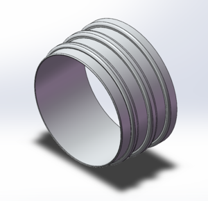
Fig 1. Drum

Objectives
- Design the Drum drive and volume of drum
- Modify the mounting location for sensor
- Design motor support
- Design the top of heat exchanger cover
- Draw CAD files of several EE components
- Animation of drive mechanism
Constraints
- Dryer size does not exceed 250x220x300mm.
- At least 0.5 L capacity, able to dry a cotton handkerchief, size 15 x 15 cm (± 3 cm) within 1 hour.
- The motor support should exactly fit the motor and could be fixed on the bottom of the dryer.
- The sensor mounting should be safe and suitable.
The design
Drum Size

The design of our drum adopts a pattern of "narrow front and wide back". This drum is tapered 2 degrees from the back to the front and the diameter of the front circle is relatively smaller than that of the back one. The reason for this is that the structure can usefully improve the thermal reflux which help dryer perform better on energy recovery. There are 3 tracks on the surface of the drum which could fix 3 belts simultaneously, this design alleviates the instability when the drum rotating.
According to the capacity equation of truncated cone:

where h is the depth of the drum, R is the radius of the back circle and r is the radius of the front circle.
In our design, the depth of the drum is 65 mm, the larger radius is 48.95mm and the smaller radius is 47.79mm. The capacity of this drum is around 0.478L. Figure 1. and 2. demonstrate the basic design of the drum.
Drive Mechanism
The design we chose for the drive mechanism is Belt and Pulleys, which is composed of 3 belts and 2 pulleys as shown in Figure 3. 4. and 5.
Figure 3. and 4. show that we have designed two pulleys - one has 1 track, and the other one has 2 tracks. We mount these two pulleys in front and back of the motor respectively to allow the pulleys equip maximum 3 belts for the corresponding tracks of the drum(The 3 tracks are unconnected) . Not only that they could ensure the stability of the drive mechanism, but they also are independent to each other in operation and considerably improve the stability of the whole machine.
Compared to the gear and chain drive, the drawback is that the efficiency of Belt and Pulleys drive is much lower. However, by considering the common application for a clothes dryer-appliance, we agree that noise reduction is more important than the efficiency of the dryer.


This video shows a simulation of rotation of our drive system.
Motor Support
The final design of our motor support is shown in figure 6. We use four triangular ribs in the corners to support the container, since triangular is the most stable structure. The motor could be held vertically in the container at the top, and fixed via four screws as shown in the figure. Furthermore, this motor support could be attached on the clothes dryer through the four holes on the bottom by another 4 screws.


.png)
Top of Heat Exchanger Cover
It can be seen from figure 7 and 9 that we designed the top of the heat exchanger cover to best fit the given part of the heat exchanger cover. In addition, as shown in figure 8, we designed a lid for our heat exchanger cover top, and left several holes for the incoming air passing through uniformly. This lid is designed from the sensor mounting.


Sensor Mounting
As shown in Figure 10 and 11, we choose the model AM2303 as the humidity and temperature sensor and designed a support in order to mount this sensor inside the clothes dryer.
We decide to install the sensor on the mounting card of heater, so that it can measure the temperature in real time. For safety consideration, one more sensor is installed on the lid of the heat exchanger cover where this sensor could monitor the temperature and humidity of the air inlet to prevent backflow of hot air from damaging the device. We also left an opening at the back of the sensor mount to allow the sensor connect to breadboard and transfer data. The support of the sensor is fixed on the lid by two screws. Figure 12. shows the isometric view of the sensor mounting.


.png)
CAD Drawings of EE Part
The CAD drawing of part of EE components including breadboard, wires and power adaptor are demonstrated in figure 13, 14 and 15.


Final design of mechanical parts
This video is the "walk through" animation of our final design of mechanical part.
Recommendations
Common:
There are several things we could do to make the mechanical part better in the future. For the drum, it is suggested that we could optimize the scale of both the front and the back circle based on the performance to maximize, or even a thermal imaging could be used, to maximize the capacity and efficiency. Stainless steel instead of plastic could be used as the material to improve the service life of motor support because of its strength, ability to withstand high temperature and corrosion resistance. In addition, we use AM2303 as the temperature and humidity sensor in our design, it could also be improved by changing to a wireless sensor, which is safer and more convenient.
Abrasion:
Abrasion would easily occur on the air duct since a defect of our drive system design -- the drum is closely contact with the air duct. We consider that adding a cushion between these two items may tackle this question effectively.
Placement of sensor:
We know that it is better to place the sensor as far as possible from heating elements, but in this project, we could not find another appropriate place to mount the sensor instead of the mounting card of the heater due to the limited space. Extra space is necessary between the drum and the air exchanging system for the mounting of sensor and other demanded modules.
Electrical/Electronic Design
Requirements
Functions
- Circuits can provide adequate power for enough heat to dry clothes.
- The dryer can adjust the speed, heat, and time according to the user's orders.
- Fit-to-Condition programming code to control feature.
Objectives
The design objectives of the Electrical/Electronic sub-team are to create an Arduino program-based circuit board that meets the required conditions. The circuit board consists of a heater, sensor, motor, and fan. Electrical circuits should be safe and efficient.
Constraints
- Safety issues and electronic components that could be lost should be prevented. To do this, electrical circuits must be designed according to the rules and appropriate parts must be used. (Example. Capacitor)
- The Arduino code should be efficient and understandable for anyone.
- Every component should be operated at the same time.
- Designed with limited resources(only limited services are provided).
Alternatives
| Design | cost | Ease of connection | Heat Loss |
|---|---|---|---|
| Constant drum speed | Low | Easy | Low |
| Speed varies from low to high and keeps repeating | High | Difficult | High |
| The speed of the element changes according to the value of the sensor | High | Difficult | High |
The group has designed two different connection methods. The first method is to change the speed of the fan by changing the connection mode and adding resistance. The members of the group connect the heater and the fan on a pin and connect the fan and a resistance in series.
The second method is the traditional method of connecting three different components to different pins.
After switching on the power, the first method could cause some electronic components to heat up and the circuit to fail, so the feasible second method of connection was adopted.
The Design
Resources
Electric components, Arduino Uno board, breadboard
What is Arduino...[1]
Power supply
Description:
On the breadboard, a rectifier is used to convert 12V AC to 9V DC(The heater is powered by a 12V AC). Several electrical components such as LED, resistor, capacitor, are used in the circuits. Hence, LEDs are used to indicate the operating status of the system so that users can determine whether the power is connected or not. Capacitors are used to protect circuits by smoothing the humps of electric current.


Fan Circuit
Description:
The fan circuit is powered by a 9V DC output from the power supply. To adjust the fan speed, pin 8 from Arduino is connected to the fan circuit. MOSFET is used to control and switch fan based on output of Arduino. A diode is used to maintain current direction, and a capacitor is connected in parallel with fans to ensure safety of the circuit.
There are two ways to control the speed of the fan. The first is to control the speed by code, and the second is to reduce the voltage of the fan and increase the resistance to reduce the electrical energy obtained by the fan. After many experiments, the first method was used because if more resistors and transistors were in series in the circuit, the energy of some electronic components, such as resistors and LEDs, would be unsaturated and cause heat damage. The first method changes the duty cycle of the Fan pin, which causes a corresponding change in the duty cycle of the voltage across the fan.


Drum Motor Circuit
Description:
The drum motor circuit is powered by a 5V DC output from Arduino. To control the speed of the motor, pin 10 from Arduino is connected to the motor circuit. MOSFET is used to control and switch motors based on output of Arduino. A diode is used to protect the MOSFET during switch off, and a capacitor is to reduce voltage fluctuation of the electrical supply.


Heater Circuit
Description:
The heater circuit is powered by 12V AC. AC is used because the direction of current does not affect the generation of heat in the circuits. To control the operating time of the heater, Arduino's pin 9 was connected to the motor circuit. The capacitor C7 and resistor R6 form a snubber to ensure that the triac T1 switches off reliably when commanded to do so. Since the capacitor is connected to 12V AC, a capacitor with a high tolerance to peak voltage pulses is used for circuit safety. The heater is controlled by Arduino and the sensor is connected to the circuit, so the program can control the operation of the heater according to a return value from the sensor.


Temperature and Humidity Sensor

Description:
Temperature and humidity sensors return the temperature and humidity of the current environment as a value and provide the value to Arduino boards in real time. The sensor uses 5 blot dc output from the Arduino, and the value is sent to the program using pin 12.
Code(Value Reading from Temperature and Humidity Sensor)
DigitalValue=analogRead(sensor1); //read the voltage number on the sensor
ResistanceValue = a * (b / DigitalValue) * N; //use specific formulae to calculate the resistance of sensor
Temperature = n; humidity = m; // use formulae to turn resistance of sensor into temperature and humidity
Serial.println ( Temperature humidity ); //print the temperature on the screen
delay(1000); //delay one second
Flow Chart and Arduino Operation Code

Video of Fan and Motor
Recommendation
There are several improvements that can help the EE team better complete this project:
1. Before making the physical circuit connection and powering up, run the simulation with Tinkerpad to prevent the electronic components from burning out due to the short circuit or the resistance is too small.
2. When connecting different components, it is best for members to use wires of different colors to represent different circuits. This will help readers and team members to inspect and visit the project more clearly.
3. When connecting various electronic components, members must pay attention to completely insert the electronic components into the breadboard to prevent poor contact from causing the circuit board to burn out or the electronic components cannot work.
Structural Design
Requirements
Functions
The functions of the structural sub-team is to design the dryer to get it ready to work. For this, the doors are designed in such a way that the clothes do not fall out. It has been tried to ensure that the water collection tray collects the water while the dryer is running. Buttons are placed for user operations.
Objectives
1. Openings: The spaces on the enclosure that will be used to manage LCD, control bottoms and any other functions.
2. Door: The door of the Energy Recovery Dryer.
3. Enclosure: The outmost frame of the dryer that covers the dryer and any other functions.
4. Water tray: The water tank, which is used to collect water.
· Capacity: The capacity of enclosure needs to be large and convenient to include all of the components, materials on dryer.
· Design: The design of objectives should be convenient and can be easily reached by users.
Constraints
· Safety: The safety of dryer or design should achieve to prevent any other possible danger.
· The components should be simple to work.
The design
Enclosure
Description:
The design of the enclosure is created by providing small height and large width. The main purpose of the design dimension is to allow users to use it more conveniently. The design should be fit so that it covers dryer and any other components. In addition, it is designed to take up less of customers’ space and make it more efficient. Furthermore, the right, left and top sides of the enclosure are designed to be transparent so that the user can easily see inside. The upper part of the enclosure contains instrument panels and bottoms so that the user can view control information.


Openings
Description:
The design of opening is created by fillets the edges. The reason of design is not just the visual transition but the aim is to provide safety of users and create an aesthetic. We aimed to provide convenience to the users when choosing the location of the openings on the panel. To avoid erroneous operations, the LCD screen should be easily visible to users and the control buttons should be easily approached by users. In addition to the space in the upper right, a degree indicator can be added so that users can observe how many degrees it is. Furthermore, from the circle in the middle, they can see the interior, which provides a pleasant view.


Door
Description:
There are two types of doors: One is circular and the other is rectangular. Both doors are made of translucent material so that users can see the condition of the clothes inside the drum. Although both design types are useful today, the rectangular design has more visible space so that users do not have difficulty when they want to put something inside. The biggest reason for choosing a rectangular door is that it provides a larger space to take off or put clothes when opened. On the other hand, the round door provides a more aesthetic and modern show. It is also comfortable and reliable. Users have the freedom to choose according to their wishes. The objective of the door is to help users to put clothes inside of the dryer.


Latch
The latches are designed to lock the door and prevent any leaks while the dryer is running.
In this way, comfortable and reliable use of the dryer is offered to users.


Water Tray
Description:
A container is designed to collect water for the water tray. It was planned to place it in an inconspicuous place under the dryer so that people can easily remove it. Thus, it was ensured that it does not give an uncomfortable appearance when viewed from the outside. Since our door is rectangular, the water tray is designed differently and made circular without edges. The water tray is circular designed to take in more water and have a larger volume, which makes it safer and easier to use.


Conclusion
The final product is a solid dryer that works by recycling heat and drying clothes with less energy consumption than tradition dryers. As been described, it has 3 buttons to manualize temperature, time, and humidity of the dryer. It has a "narrow front and wide back" shaped drum for a better efficiency of energy recovery. Knowing about the features of the designed dryer, it's a better option for people who's intentions to contribute in a sustainable world. Aside from energy consumption, this designed dryer consumes up less time which perfectly meets the needs of people with limited time such as professors, doctors and others.
Virtual and Actual Prototype Demo
The videos are found in each sub-team.
Live Chat
We will be glad to see you on our presentation. Choose the time and join in. Contact us if you need any help.
| Day | Time | Presenter | Presenter | Presenter |
|---|---|---|---|---|
| July 12 | 2:15 -3:15pm | Asli | Berke | Doyun |
| 3:30-4:30pm | Yousef | Minghao | Andrey | |
| 4:45-5:45pm | Yifeng | Andrey | - | |
| 6:45-7:45pm | William | Junhyung | - | |
| 8:00-9:00pm | William | Junhyung | - | |
| July 13 | 11:15-12:00pm | Asli | Berke | Doyun |
| 2:15-3:15pm | Yifeng | Yousef | Minghao |
https://gather.town/app/9qz0rUQdriDf0flT/Vantage%20%20Capstone%202021
About us
| Documentation | |
|---|---|
| Yousef Mohamed
E-mail address: yousef.hussein2000@hotmail.com
|
 Andrey Abushakhmanov
Andrey is a Vantage College of Applied Science student. The capstone conference has been a great opportunity to practice communication and team skills. His team was responsible for the documentation of all parts of the project and the creation of the wiki page and presentation. Andrey is very glad to have an opportunity to work with the great partners on the same exciting project. |
| Electrical / Electronic | |

E-mail address: ol01y03@student.ubc.ca Electrical/Electronic Sub-Team contributor
DoYun Kim is currently studying applied science at UBC. She mainly contributed to designing a circuit board for the dryer that operates the motor, fan and heater using an Arduino. She is responsible for communicating with other team members. DoYun Kim is from Korea, and loves to watch movies. She was able to learn academic knowledge and communication skills through this project. |
William Hui
E-mail address: huiyihan1009@163.com Electrical/Electronic Sub-Team Contributor
He is currently studying Applied Science at UBC. He is responsible for all the work related to circuit connection photos, codes and flowchart drawing. He learns a lot about how to cooperate with others and knowledge about Arduino from this project. |
| Mechanical | |
| Minghao Zhou
Mechanical sub-team member Contact Information: zmh01@student.ubc.ca As a member of Mechanical sub-team, Minghao is responsible for the motor support, sensor mounting and heat exchanger cover design. Also, he contributes to edit the wiki page of his sub-team. During the process of designing this project, he has learnt the basic skills of using Solidworks and improved the ability of time management and team cooperation. He believes that this 8 weeks memorable experience will definitely benefit him in future engineering design. |
Yifeng Liu
E-mail address: 13434213656@153.com
of drum and drive system, the design and modeling of EE parts and the final modification and assembling of each design. He also contributes to edit the wiki page of his sub-team. His great achievement from this project is that he learned a lot of basic conspects of different engineerings and the primary understanding of what an engineer's work will be. He beileve this will be an irreplaecable experience for his study of engineerings.
|
| Structural | |
 Asli Tuncer
Structural Sub-Team contributor Asli Tuncer is currently studying applied science at UBC. The capstone conference has been a great opportunity to learning team work, making presentation. She mainly contributed to designing structural components. She is responsible for communicating with other team members. Asli Tuncer is from Turkey, she is very grateful to learn academic knowledge and communication skills. |
 E-mail address: mberke27@student.ubc.ca Structural Sub Team Contributor Berke Karadayi is currently studying applied science at UBC. The capstone conference has been a great opportunity to improve team working, communication, presentation skills. He mainly contributed to design structural components. He is responsible for communicating with other team members. Berke is very thankful to work with the great team mates during the project. |
| User-Interface | |
| Junhyung Han
E-mail address: hjh00062@student.ubc.ca User-Interface Sub Team Contributor Junhyung Han is currently studying applied science at UBC. The capstone conference was very helpful by experiencing teamwork, presentation, and all the processes in person. He mainly contributed to User-Interface designing. |
|