Course:VANT151/2020/Team6/Team6Main
Home
Welcome to (Energy Recovery Clothes Dryer)
Welcome to Energy Recovery Clothes Dryer! Our research team consists of 13 people, Rice, Coco, Bill, Roop, Subin, Kristina, Jorge, Roy, Erich, Brianna, Shirley, Crystal and Malinee, who is skilled in documentation, electronics, structural, mechanical, UI design and thermal. Our objective is to discover a new way to reuse heat and to improve the overall process of the clothes dryer. Therefore, we come up with “Energy Recovery Clothes Dryer”, redesigning the motor, fan, heater, drum drive, heat exchanger cover, enclosure along with an easily controlled and practical user-interface, as well as adding temperature and humidity sensor in order to give user a precision and convenience in the process.
Project Overview
Problem Statement
Energy Recovery Clothes Dryer The normal clothes dryer should have an alternative way to reuse the heat from warming clothes, not to let them lost and useless. In other word, to sustainably reuse an energy with an effective approaches and designs. Our overall project objective is to design and fabricate the components, new feature and assemble a 1:3 scale model of a Clothes Dryer with an effective heat and airflow to evenly dry clothes by using the equipment provided by the professor and will be testing by the capstone conferences.
Project Function
1. The clothes dryer can evenly dry clothes with the rotation of drum drive.
2. The clothes dryer can reuse the heat from the drying process.
3. The clothes dryer can store the heat for the next drying process.
4. The clothes dryer can automatically measure the temperature and humidity of the clothes.
5. The clothes dryer can dry the heat with the customized temperature.
Project Objective
1. The drum drive should be consisted of motor, pulleys and belt.
2. The clothes dryer should evenly and completely dry clothes
3. The clothes dryer should have a capability to reuse the heat from the drying process
4. The clothes dryer should be silent.
5. The clothes dryer should have a comfortable mean of access.
6. The clothes dryer should have convenient location of the control panel.
7. The enclosure of the clothes dryer should be created from sustainable materials.
Project Constraints
1. The dimension of the clothes dryer must not exceed 250 x 220 x 300 mm (fit within carton for copier paper).
2. The clothes dryer must dry 0.5 L a cotton handkerchief within 1 hour.
3. The electrical power consumption must not exceed 12V AC, 12 VA.
4. Alphanumeric LCD display and a navigation buttons for user interface.
5. Automatic operating mode
6. Manual operating mode: able to set desired
- Drying time
- Temperature
- Dryness.
Final Report can be accessed from here https://drive.google.com/file/d/12CIdGd_P8b71FZf8Pz-AjFACO7B-hIDt/view?usp=sharing
Presentation can be accessed from here
Mechanical Design

The mechanical components of the dryer are the motor, drum drive, pulleys and the temperature sensor. The mechanical sub-team is responsible for designing a functioning drum drive with a solid motor support for the dryer. The drum is the main component of the dryer. The drum is rotated by a drum belt. The rotation of the belt is supported by two pulleys, the drive pulley and the tension pulley. The drive pulley drives the belt and the idler pulley provides tension. The tension pulley is designed to stop the motor from running when the drum belt is broken. The rotation of the drum allows heat and airflow to dry the clothes efficiently and evenly. The drum is supported by glides and front rollers on the outside. An additional feature is the temperature and humidity sensor.

Requirements
Functions
- The clothes dryer allows heat and airflow to dry the clothes efficiently and evenly
- The designed baffles rotate and lift the clothes
Objectives
- Designing a functioning drum drive which is the main component of the dryer for the dryer.
- Motor
- Pulleys
- Belt
- Extra Features
Constraints
- Limited equipment
- Tight timeline
A motor and its mounting - The drum volume must be greater or equal to 0.5L
- The clothes dryer must dry the 0.5 L of clothes within 1 hour.

The Design
Drum Size
The drum volume is approximately 0.5L. The diagram below shows the basic design of the drum (front and back rings are attached). The drum is designed to dry a small piece of clothing in a short time. It is also decided to rotate at a desired speed. The scale of the drum drive with the volume of 30cm^2. The final design for mechanical parts

Drive System and Motor Support
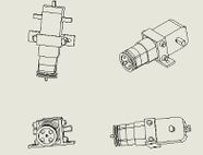
A motor will be used for the drum drive to provide rotation. The mounting position of the motor will be on the outside of the drum, on the bottom panel. Additional support will be built to support the motor. A bracket is used to secure the motor from slipping. Two pulleys will be used. The first pulley (figure 6) is called the drive pulley, which would be used to drive the drum. It is attached at the front of the motor. The second pulley (figure 7) is the tension pulley, which will be used to provide tension for the belt and prevent it from slipping. The tension pulley is placed next to the motor, and it has a base support that is attached on the bottom panel. Figure 4 and 5 are two design alternatives for the connection of the two pulleys. The final design is as shown in figure 5: the two pulleys are connected in a zig zag direction so that the tension pulley can provide sufficient tension for the belt. The belt will first go around the drum, through the drive pulley and the tension pulley.
Temperature and Humidity Sensor
The extra feature will be attached to the backboard of the drum. Extra screw holes will be designed as well.


User-Interface Design
Requirements
Functions
1. Switch on and off the washer with a power switch
2. Able to display and respond to user action
3. Have multiple washing mode for selection
4. Have a timing function.
5. Receive signals from the sensors to ensure the door is closed
6. Have a reminder alarm
7. Able to switch off without operation done for a long period
Objectives
1. Have nice UI design (keep reading the buttons until user stop pressing)
2. Have a reasonable washing and drying time
Constraints
1. The size of the UI system should not be bigger than 100x150x60 (mm) (including the LCD display)
2. The power consumption of the entire system should not exceed 3 watts (when turned on).
3. The power consumption of the entire system should not exceed 0.5 watts (when turned off).

The Design
Hardware Layout
The design has 5 buttons, one switch, one buzzle, and two LEDs. For that design, four buttons are for selecting the objects as cursors, and one is used as a confirm button. At the right of the five buttons, a switch and two LEDs were installed for switching on/ off the dryer and indicate the working status of the dryer.
Operating Sequence and Program Flow Chart
The dryer has three drying modes for the user to choose, Auto, Quick Dry, and Customize. With auto mode being selected, the dryer will sense the weight of the clothes automatically and calculate the time required, in this mode, temperature and humidity will be set to standard at 40 degrees and 50%. Following with the quick-dry mode, with this mode, the dryer will start the drying procedure with maximum temperature and rotation speed and minimum humidity. For people who wear flimsy clothes, they can select the Customize, where they can select the temperature, rotation speed, and humidity.
Structural Design


Door animation of the overall design.


Requirements
Functions
Structural sub-team is responsible for the modified, optimized, and precision drawings of the dryer itself (the enclosure, various openings and holes, door and latch); creation and testing of the animation of the mean of access using Computer-Aided Design (CAD). CAD files of UI parts (LCD, buttons) also should be presented by structural sub team.
Objectives
- The Clothes Dryer should be silent.
- The Clothes Dryer should have a comfortable mean of access.
- The Clothes Dryer should have convenient location of the control panel.
- The enclosure of the EneRec Dryer should be created from sustainable materials.
Constraints
- The size of the EneRec Dryer does not exceed 250 x 220 x 300 mm (fit within carton for copier paper).
- The EneRec Dryer should have an alphanumeric LCD and a navigation buttons for the user interface.
The Design
Enclosure
The enclosure is made of plastic and stainless steel. In future work, these materials should be replaced by the more environmentally friendly ones.
The overall size is 250 x 217 x 270 mm. In addition, this design has holes on the back and right panels to provide an opportunity to allow air to enter a dryer.
The designs is big enough to follow the constraints and at the same time allows having all the parts of dryer in the right position. The dryer has a rectangular shape with curve edges so the grip and mobility are easier to manage; it has four legs at the bottom which gives stability to the design.
Door
As it can be seen, front load dryer with circular door was chosen.The diameter of the door is 102.6 mm. According to the conducted research, a drum in a front load usually spins faster, giving an opportunity to speed up the drying process. Front load dryers use about 1/3 energy of top loading, making them more environmentally and utility bill friendly. In addition, front load dryers are the quietest and most accessible for the user to put the cloth inside.
Location of Control Panel

Based on the team member preferences, it was considered to put in the front right corner of the dryer. Our team decided to choose a front dryer; consequently, if the UI is put on the top of the dryer, it would be uncomfortable for the user. The dimensions of the UI are 40 x 80 x 3 mm.
Water Collection Tray
The water tray was design with the dimension of 9.00 mm of depth, 75.00 mm long and 34.80 mm wide. The design is a rectangular platform with a semicircular platform at the top, thus it fits perfectly where under the HX outlet. The dimensions of the depth give enough space for the water to accumulate and for the tray to fit inside the dryer.
Electrical/Electronic Design
The circuit design operates a heater, a motor, a fan based on the readings of a humidity sensor connected to the Arduino board. The circuit uses AC current, and other electrical components like wires, capacitors, mosfets, resistors, LED etc. are used to make connections in the circuit. These components are connected in such a way that system works efficiently without compromising the safety. For example, LED indicates the flow of current while resistors control the flow of current, whereas mosfet amplifies electronic signals. These electrical functions are coordinated using a custom programming code written in the C programming language. The code is provided further in the report. This circuit design satisfies the basic requirements i.e. the electrical system must be compatible with other systems and system needs to be safe, easily maintained, and efficiently complete instructions given by users. However, the components are limited to the types provided by the professor and the system needs to be compact as we are designing a smaller scale model of dryer. So, in order to make this circuit design stand out the of the basic design provided so modifications were made which would be explained further in the report.
Requirements
Functions

- Circuit is able to provide an enough power to dry clothes
- The circuit is efficient without compromising safety
- Customizable programming code to coordinate feature
- Clothes dryer contains humidity sensor to ensure atomization of the process.
- Clothes dryer can adjust speed, heat and time.
Objectives
- The design objectives of the electrical/electronic sub-system are to create a circuit board that is compatible with heater, sensor, motor and fan operated by a custom program
Constraints
- Design is not waterproof
- Designed out of limit resources so not competitive with current market designs.
- Being a prototype might fail to work at a larger scale with current design.
The Design
The circuit design operates a heater, a motor, a fan based on the readings of a
humidity sensor connected to the Arduino board. The circuit uses AC current, and other
electrical components like wires, capacitors, mosfets, resistors, LED etc. are used to make
connections in the circuit. These components are connected in such a way that system
works efficiently without compromising the safety. For example, LED indicates the flow of
current while resistors control the flow of current, whereas mosfet amplifies electronic
signals. These electrical functions are coordinated using a custom programming code
written in the C programming language. The code is provided further in the report. This
circuit design satisfies the basic requirements i.e. the electrical system must be compatible
with other systems and system needs to be safe, easily maintained, and efficiently complete
instructions given by users. However, the components are limited to the types provided by
the professor and the system needs to be compact as we are designing a smaller scale
model of dryer. So, in order to make this circuit design stand out the of the basic design
provided so modifications were made which would be explained further in the report.
Power Supply
As can be seen in the schematic, the power supply takes in 12 volt alternating current and transforms it into 9 volt direct current using a bridge rectifier and a DC-DC power supply. Several capacitors are used to smooth out the current. The 9 volt ac is then used to power up the Arduino board and the whole circuit.

Fan Circuit
As can be seen in the schematic, pin 9 from the Arduino is connected to the fan circuit to control the speed of fan. 9 volt dc output from the power supply is used to power up this circuit. A MOSFET is used to control the fan's operating voltage based on the output of the Arduino. A diode is used to prevent short circuit and a capacitor is connected in parallel with the fan to ensure its safety.
Drum Motor Circuit
As can be seen in the schematic, pin 10 from the Arduino is connected to the motor circuit to control the speed of motor. 5 volt dc output from the Arduino is used to power up this circuit. A MOSFET is used to control the motor's operating voltage based on the output of the Arduino. A diode is used to prevent short circuit and a capacitor is connected in parallel with the motor to ensure its safety.
Heater Circuit
As can be seen in the schematic, the heater is powered up by 12 volt alternating current. As the direction of current doesn't affect the generation of heat, ac is perfect for this circuit. A safety capacitor is used to ensure the safety of circuit. The operation time of the heater is controlled by Arduino from port 8.
Temperature and Humidity Sensor
The temperature and humidity sensor takes in the current temperature and humidity of the current environment and gives an instant feedback to the Arduino board. It uses 5 blot dc output from the Arduino and sends the collected data to Arduino board using pin 12.
Thermal Design

Requirements
Functions
- The heat exchanger is a system used to transfer heat between two or more fluids. Heat exchangers are used in both cooling and heating processes. The fluids may be separated by a solid wall to prevent mixing or they may be in direct contact. This heat exchanger is going to transfer heat from hot air to cold water to heat the water into hot water.
Objectives
The heat exchanger always has a constraint that the inner tubes would be dirty after used for a long time and hard be cleaned. Due to this, the thermal conductivity of the inner tubes would be greatly reduced which would influence the use of heat exchanger. The objective of the product is
- To design a heat exchanger for providing enough heat to improve the efficiency of the dryer.
- The tubes and shell should be easy to clean
Constraints

Heat is necessary for efficient dryer operation.
- Able to heat up at least 0.5 L air
- The air heated should be able to dry a cotton handkerchief with 1 hour
- Maximum allowable electrical power consumption: 12 V AC, 12 VA
The Design
Heat Exchanger
The type of heat exchanger used in our dryer is the shell and tube heat exchanger[1]. The heat exchanger is a system used to transfer heat between two or more fluids. Heat exchangers are used in both cooling and heating processes. For here, the heat exchanger is going to transfer heat from hot air to cool air. This design makes the fluids be separated by a solid wall to prevent mixing to make sure the air into the drum is hot and dry. Several tubes increase the heating area and the efficiency of heat transfer.

The air used in the drum is always warm and moist, it could take out the moisture from the clothes. after it enters the tubes, it starts to provide heat to the cool air and its own temperature starts to drop. in this process, this hot and moist air becomes water gradually. then, it is discharged through the water collection tray. the incoming cool air is heated into hot dry air and enters the drum got drying clothes. this process improves the overall energy efficiency of the dryer.
The image on the right (Heat exchanger in SOLIDWORKS) shows the heat exchanger in our energy recovery dryer. Thermal sub-team collaborated with mechanical sub-team to create a heat exchanger cover (the green top on the right figure) and a hole on the back for the cool air to come in. The copper tubes inside are used to carry the hot moist air coming out from the drum. At the same time, there's heat transfer between the cool dry air and the hot moist air; that is, when the cool dry air coming inside through the outer tube, the hot moist air in the copper heats up the cool air. By doing this, we may have warm dry air in the drum again, while the moist air cools down go to the water collection tray.
Solidworks Flow Simulation
_in_the_heat_exchanger_(right_plane).png)
Here're some images of the flow simulation of a heat exchanger. The flow simulation is created by using the flow simulation tool in Solidworks. After input all the required data, we ran the calculation and get the result. This image show that the air flow according to temperature. We can see from the first figure that different colour represents different range of temperature. The flow simulation aims to give the user a better understanding of how the heat exchanger works. The second image shows the isometric view of the flow simulation.
_in_the_heat_exchanger_(isometric).png)
The flow simulation also can be used to see the speed of each part of the flow. The third image gives an example to present the air flow according to the velocity.
_in_the_heat_exchanger_(isometric).png)
Virtual and Actual Prototype Demo
This VDO shows how the electrical component work with Fan and Drum Drive
This VDO demonstrates on the operation of the user interface panels
This VDO represents the animation of the door
Live Chat
We are on duty during capstone hours during capstone hours according to this roster
Feel free to be in touch with us through Collaborate Ultra
| DAY | TIME | Presenter | Presenter | Presenter |
|---|---|---|---|---|
| DAY 1
13 JULY 2020 |
11:15 - 13:15 | Crystal | Brianna | N/A |
| 13:15 - 15:15 | Bill | Roop | ||
| 15:15 - 17:15 | Kristina | Subin | ||
| 17:15 - 19:45 | Shirley | Erich | ||
| DAY 2
14 JULY 2020 |
8:00 - 10:00 | Hutsawat | Malinee | |
| 10:00 - 12:00 | Jorge | Coco | Roy | |
| 12:00 - 13:15 |
About Us
Sub-teams:
| Documentation | |
|---|---|
 Documentation, Editor Hello, you can call me as "RICE" in stead of my long name. I was positioned in this team as a documentation and editor who combined every sub-team work and produced a report. I have gained many experiences from the team and project management. |
 Documentation Sub-Team member Hi, I am Coco and I am from documentation sub-team. I am mainly responsible for collecting all the information and results including sketches, values, figures from other sub-teams and completing final report. I learned the standard format of writing a project report. Also, my communications skills while cooperating with other team members was enhanced. |
| Electrical/Electronic | |
 Electrical Sub-Team member I am Bill from the electrical sub team. In this project I mainly contributed to the electrical components of the dryer as well as writing controlling program. In this special experience, I have learned the basis of designing a simple circuit. Also my teamwork skills are enhanced. |
 Electrical Sub-Team member Hi, I am Roop from electrical sub team. For this project I contributed in designing a circuit board for the dryer that operates motor, fan and heater using a custom C-code and Arduino. Also, I contributed in finding alternatives to improve our initial design and add additional features like heat sensor for atomization. This project helps me to learn the importance of teamwork, and also gained knowledge about the working of different electrical components in coordinating functions. |
| Mechanical | |
 Mechanical Sub-Team member, Team Leader I am Crystal from the mechanical sub-team. I am responsible for designing the drum drive mechanism and the motor support. I helped with finalizing the CAD for the whole dryer. I learned a lot more about 3D design, project management and team collaboration from this capstone project. |
 Mechanical Sub-Team member am responsible for designing an extra feature as well as designing the motor with extra support. From this project, I become more comfortable with Solid Works and have gained some teamwork experience. |
| User-Interface | |
 User-Interfsce Sub-Team member This is Roy, from the user interface sub-team. I was in charge of the software programming and function testing. Through this project, both my programming and circuit design abilities were advanced. Besides, communication and reporting skills were also improved. |
Erich Yu
User-Interface Sub-Team member I was in charge of the software design part and choosing the basic layout of the operation panel design. Through this project, both my programming and electric circuit design abilities were improved. In addition, through this group design process, communication skills is also improved. |
| Thermal | |
 Thermal sub-team member I am Brianna Zhao from the thermal sub-team. I am responsible for the design of the heat exchanger, the creation of flow simulation and the animation of the air flow. I found it really useful to learn more about CAD model using SOLIDWORKD. I’ve learned a lot collaborating with other team members to work on a same project. This capstone conference is definitely the highlight of my Vantage One program. |
 Thermal Sub-team member I am Shirley from thermal sub-team, I am responsible for the design of heat exchanger. From this project, I learned the use of SolidWork and the process of applying theoretical knowledge to real design. At the same time, I also knew the importance of cooperation among team members. |
| Structural | |
 Structural Sub-team member Hi, I am Subin Jang in Structural Sub-team. In this project, Structural sub-team contributed to designing the dryer, sketching the drafts and making a 3d feature of the dryer. I was mainly responsible for drafting the ideas into the sketches and making an animation of the 3d model of the dryer. I have learned how to communicate well with other team members to come up with good ideas and output. Also, I got used to use the SolidWorks program. |
 Structural sub-team member I am Kristina from the structural sub-team. I was responsible for the designing and building of the front panel of the EneRec Dryer, including the door and UI part. In addition, I created openings of the dryer: water collection tray opening and opening for the cool air of the heat exchanger. Also, I drew the final CAD of the UI and the whole dryer. This project developed my teamwork skills and gave opportunity to become familiar with SolidWorks software. |
Jorge Rivera Hello I’m Jorge Rivera, my contributions to the project were desiging the door and the control panel position in the dryer. I learned to use Solidworks as a tool for my future designs. |
|