We are research team #3 from VANT151 section 1. Our goal was to design and contruct a prototype of an Energy Recovery Clothes Dryer (EneRec Dryer) that may effectively reduce the electricity consumed to dry up clothes.
Project Overview
Energy Recovery Clothes Dryer (EneRec Dryer)
This project is to design and build a scaled-down prototype of an Energy Recovery Clothes Dryer for project testing by 14 July 2020 with the given kits of components and online software. The delivery contains the electronic and user-interface components while the online software includes SolidWorks, Arduino and TinkerCad. The EneRec dryer to be developed focuses on reducing unnecessary waste of heat energy and put them into second use. Unlike the conventional ones, which consumes vast amount of electricity to heat up cold dry air, the EneRec dryer utilizes the combination of heater and recycled hot wet air to dry the clothes in the drum.
Electrical/Electronic Design
Lists of electrical components
Motor
Fan
Heater
Temperature/humidity sensor
Requirements
Functions
Means to monitor and record the temperature and humidity
Heater to heat the clothes in the dryer
Means to rotate the drum constantly
Constraints
The maximum allowable electrical power consumption is 12 V AC, 12 VA.
The voltage on the outside shell should be non-harmful to human body (Less than 36 V).
Objectives
High power efficiency
Short drying time
Little damage to clothes
The Design
Power source
The safety, cost and convenience can be modified when different power sources are used. Therefore, in order to optimize the electrical components of our dryer, we tested 3 different power sources, including 12 V AC, 12 V DC (converted by rectifier), and 5 V DC (powered by USB ports).
Table 1.
12V AC
12V DC
5V DC
Safety
S
1
1
Cost
S
-1
-1
Convenience
S
-1
-1
Sum
0
-1
-1
According to the table above, both the 12-power AC source is the best choice. The 12 V AC is not extremely safe and stable but enough for formal use. The 12 V AC power adapter of the power source is more affordable than its competitors’. Also, the 12 V AC power source is convenient since it does not need an external rectifier, which means that the dryer will be much easier to be transported and installed when the 12 V AC is applied. Therefore, we finally choose the 12 V AC power source as the one used in our circuit.
Direction of motor rotation
The direction of motor rotation of the dryer is also a factor that has influence on the cooling performance of the dryer. We decided to make a selection from 2 potential solutions, single direction and di-direction. The list of alternatives and corresponding descriptions are shown as the followings:
Rotation in single direction:
Simple structure
Low cost
Possible entanglement of clothes
Rotation in di-direction:
Relatively low likelihood for the clothes to get entangled
Relatively more area that the clothes get heated
Complex structure (Harder to repair)
The method of multi-voting is used to decide the direction of rotation. There were 5 members from our team participating in the voting. We got 4 votes for the single direction and 1 vote for the di-direction because most of us think that the low cost of the single-direction rotation can make our products more easily recognized by consumers. Finally, single direction is chosen and applied in our dryer.
Relay for the heater
A MOSFET (Metal Oxide Semiconductor Field Effect Transistor) is used for controlling and switching the loads of electrical circuits. It is a three terminal element which has source, gate, and drain. A Triac is a triode for alternating current. It is a three terminal component that is commonly used for controlling element such as power control in alternating current circuits.
As for the design of the relay for the heater, we come up with 3 different alternatives, including single Triac, single MOSFET, and the combination of both of them.
In order to make a selection among different design options, the Pugh method is used to compare several potential solutions based on a selected standard. If a potential solution makes the same performance with the standard, a “0” would be put in the cell. If it is better than the standard solution, a “1” would be put in the cell. Similarly, A “-1” would be put if the potential one is relatively worse than the standard. After summing up all the scores, the solution with the highest points would be selected as the final solution.
The triode for alternative current (Triac) is selected to be the standard solution since it is normally used for AC circuit, and the other three potential solutions are MOSFET, relay, and the combination of all.
Table 2.
Triac
MOSFET
Combination
Operation time
S
0
0
Cost
S
0
-1
Counter space
S
0
0
Versatility
S
-1
0
Sum
0
-1
-1
After comparing the total scores, the Triac is likely to be the final solution. It would be used for the power control in the alternating current circuit to control the heater. Also, the design of the use of Triac in the heater part is shown in the form of circuit schematics in Figure 1.
Figure 1. The circuit schematics for the heater part.
Sensor position
The follow list includes all the potential positions to place the sensor.
At the bottom end of the filter
At the back of the dryer door
Attached with the drum
Figure 2. The sensor at the back of the dryer door
The sensor can directly detect the temperature and humidity within the drum. The sensor would not be hindered by clothes when the drum is rotating. However, some potential problems might occur due to the position of the sensor. For instance, when the dryer door is broken and needs to be replaced, the sensor must be replaced as well. It might cause the additional cost for maintenance of the dryer.
3. Attached with the drum
Figure 3. Sensor attached with the drum
The sensor can directly detect the temperature and humidity within the drum. However, the sensor might be hindered by the clothes when the drum is rotating. It is possible that the clothes might get stuck on the sensor, resulting in the inaccuracy of the temperature and humidity data detected by the sensor. Another advantage is that cotton or other dirt from the clothes might stick on the sensor bar since the sensor is planed on the side of the drum. This problem can be solving by cleaning the dryer after every use.
The Pugh method is used to make a selection among different design options by comparing the potential solutions based on a selected standard. In this case, the solution of placing the sensor at the bottom end of the filter is selected as the standard.
Table 3.
Alternative 1
Alternative 2
Alternative 3
Accuracy
S
1
0
Cost
S
0
0
Maintenance
S
-1
1
Sum
0
0
1
As can be seen in the above table, the alternative 3 is likely to be the selected design since it gets the highest total mark.
Extra Features
Pre-rotation
Sheets and quilt cover tend to fold up and twist on themselves when they get dried in the dryer. That is because the drum of the dryer could not offer enough space for them to completely spread. To solve this problem, before the dryer starting to work, the driver can be rapidly rotated for 30 seconds. This process can make the sheets unfolded and prevent the sheets from getting tangled in the dryer. This function is achieved by the code below.
Some users might forget to take away the laundries from the drum. To solve this problem, a buzzer can be added to the electrical circuit. When the dryer has completed the working process, the buzzer would make loud trumpeting noise to reminder users that their laundries have been dried. The buzzer would keep making the sound until the user manually turn off the power. The circuit contains the buzzer can be seen in Figure 4.
Mechanical Design
Lists of Mechanical components
Drum size
Drive
Motor support
Cover for the tail of the heat exchanger
sensor mount
Requirements
Functions
The drum to hold the clothes
The drive to provide power for the drum to rotate
The motor support to hold motor on the position
The cover to fit the heat exchanger
The sensor mount to hold sensor on the position
Constraints
The Drum needs to protect the clothes from damaging during the operation of the drying machine, while it could dry the clothes efficiently.
The drive needs to provide enough kinetic energy to rotate the drum.
The motor support needs to make sure that the motor stay in a relatively stable situation when the motor is working.
The heat exchanger cover needs to cover the heat exchanger designed by the other sub-team.
The sensor mount is used to locate the sensor, so the sensors would work well and detect the temperature and humidity change inside the drum.
Objectives
Hold enough clothes
High efficiency of drying
Protect the sensor and motor
Long working life
The Design
Drum DRIVE
The initial design is a drum with equal length and diameter shown in Figure 4., there are horizontal humps inside the drum to increase the friction between the clothes and the inner surface, which aims to raise the drying efficiency. A hole is on the bottom to drain away water from the clothes However, this design has a significant drawback, while the machine is operating, all the clothes willstay at the bottom.
Figure 5. initial design of the drum
Figure 4.
To improve, our team add two vertical bars within the drum as shown in Figure 5. Those two bars could hold the clothes, and the clothes would rotate during the operation of the machine. Furthermore, more space is added to the bottom for leaking water. As shown in figure 3, there is a grove on the outer surface, and the grove is kept for the belt of the drive system.
Figure 6. front view of drum
Figure 5.
Drive
Figure 7.
Figure 6.
Two main types of drive could be used which are using belts and using gear as the transition media of the energy. The basic working principle of those two design are similar, which is using electricity to generate one small pulley and using belt or gear to transfer the energy to the drum. The way we evaluate those two design is doing some research and combine all the information on a table, here is the result in table 4.
Table 4.
Type of the drive
Cost
Efficiency
Service life
Total
Belt
1
0
1
2
Gear
0
1
0
1
During the researching process, we found out that using belt have lower cost compare with gear and the structure of using belt is relatively easier. The belt transmission is stable and absorb vibration which is good for the drum to rotate. The belt could protect the small pulley. If the rotation speed of the drum is too fast, the belt will slip on the pulley and it will not destroy the who machine. If the gear was used, then it cannot protect the small pulley and the who design will be destroyed. As a result, we choose belt as our final design.
Motor support
There are two shape of the motor support, which are the isosceles trapezoid and square
Isosceles trapezoid: The benefit of this shape is stable and it could hold the motor well. The disadvantage of this design is it need more space so that the cost of the whole project will increase.
Square: The benefit of this design is easy to produce. It is relatively easier to make a square compare with the isosceles trapezoid.
Figure 8.Figure 9
Figure 7.
The way we choose our final design is by doing an experiment. We used the same amount wood to make one square and one isosceles trapezoid. After that we put some books on the top of those two shape until the structure broken. Here is the result:
Table 5.
Shape
Number of books
Square
2
Isosceles trapezoid
3
This table shows that isosceles trapezoid is more stable compare with the square. In this project, the constraints are to keep the motor stable while it is working. After we discuss with our group member, we decided to use isosceles trapezoid as our final design.
Cover for the tail of the heat exchanger
To meet the requirement of the heat exchanger cover, first, we need to design the size of the object. The size is designed according to the provided heat exchanger. Figure 1 shows our initial design of the cover, with a suitable size. However, this design does not fit the heat exchanger, and it is not fast at all.
Figure 10
Figure 8.
Next, we need to decide the shape of the cover. We need to make sure that the cover has good gas flowability because the heat exchanger could be hot during the working process. Here is our final design.
Figure 11
Figure 9.
Sensor mount
Figure 12
Figure 10.
The sensor mount contains the body and a lid. It is convenient to use the take the sensors out or put it in.The size ischosen according to the space left in the driving machine, while the mount could be large enough to hold the sensor, it cannot occupy to much space.
Two holes are set to hold the sensors, so the sensor could function well and provide the data.
Extra feature
Acoustic material
During the rotation of the drum, the noise will be produced due to the collision of clothes and the drum. Noise can distract people from working or influence sleeping quality. So, the acoustic material can be used on the drum to decrease the noise.
Vibration damping system
The rotation of the drum would clause the vibration of the whole machine, while other components like motor resonate with the drum, they might be damaged. So springs can be used to maintain the drum and damping the vibration.
Super-stable motor control system
The vibration of the motor is one of the biggest reason why the machine vibrate. Our sub team designed a larger and more stable motor holder to make sure that the motor is as stable as possible.
Structural Design
Overview of the Structural sub-system
Requirements
Functions
The functions of the structural sub-system are designing the enclosure, door, location of control panel and water collection tray, so that the dryer could be assembled.
Objectives
enough space to contain clothes.
convenient for user to use.
Constraints
the size of enclosure not exceeding 250*220*300 mm.
the size of tray must be smaller than the enclosure.
The Design
Enclosure
The different types of enclosure are used to run the dryer and easy for consumer to place at home.There are two types of enclosure:
The first one looks like a aircraft. Clothes can be hanged in the dryer and then they will be dry. This kind of dryer can save lots of energy compared to the second one. Apart from that, it can flatten the clothes to prevent wrinkles. However, this enclosure is easy to break and its not safe compare with the second one.
The second one is a traditional dryer. Clothes can be put though the opening and drum will run after generating the dryer. The water will be connected into tray. This type of enclosure can use less space to dry more clothes and its appearance is more acceptable than the first one. According to this table, choice 2 has high score so it will be our final choice.
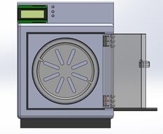
Figure 13. the designed enclosure
Figure 11.
Table 6.
Choice1
Choice2
Safety
0
1
Appearance
0
1
Practicability
1
0
Door
In general, doors and latches are inseparable. However, some kinds of door do not need the latches. There are three kinds of door can be chosen. And one of them is selected after all member voting. The list of alternatives and corresponding descriptions are shown as follows:
· Iris door: This is a kind of iris - like door. When you turn the button at the bottom clockwise, it will open like a pupil hits the light. Or, it will close like the pupil goes into darkness. This kind of door does not need a latch.
· Side swing door: When you open the side swing door, It's like the spread of wings. This kind of door need a latch. You can control the latch by the handle.
· Sliding door: The door needs to be mounted on rails. When you want to open the door, you just push the door to the side along the track. This door also does not need a latch. They can use magnets instead of latches. And the magnets can provide better sealing.
There are 10 members in our team. Each member had one chance to vote. If two design got 4 votes. We would vote again and if they got the same votes again, we would pick one at random. And after the first round we selected, the side swing door was selected. To keep the seal, we added a layer of rubber to the inside of the opening and a ring of metal holds the rubber in place on the outside of the opening.
Figure 14. the designed door
Figure 12.
Location of Control PanelF
There are three types of location of control panel:
Directly in front of the upper part of the enclosure
Front and left of the upper part of the enclosure
Figure 15At the top of the shell After consider about the convenience of the location for user, the second one is better for user to control the dryer, so it become our final choice.
Water Collection Tray
Figure 16. the choice of trayFigure 17. the designed tray
Tray is used to collect water from the drying of clothes. Different tray can contain different volume of water and take up different size of space. Three types of trays are listed in the following: Figure 13, Figure 14.
Table 7.
Type1
Type2
Type3
volume
3
2
1
acceptable
2
1
3
Tray was chosen for its volume of collected water as well as its practicality. The first one is similar in size of the enclosure. The second one can take up less space than the first one. The third one can be hanged in the dryer and catch the dried water. The volume of water that goes from large to small is that type1,type 2 type3. According to this table, the type 1 has the highest score, so it will be the final choice. The tray is located in the bottom of the inside of the enclosure.
Extra Feature
Super-stable motor support system: One of the biggest problem that the drying machine have is the vibration of it during the working process. Our team designed a larger and more stable motor holder in order to avoid the vibration of the drying machine.
A layer of rubber is placed at the opening's connection to the outside to ensure its tightness, and another foam bottom is placed at the bottom of the housing to reduce the noise and vibration of the dryer during operation
User-Interface Design
Overview of the user-interface sub-system
Requirements
Functions
There are three buttons above the LCD screen, each of them represents a different number. The blue button represents 1, the red button represents 2, and the green button represents 3. A user is asked to select a mode at the beginning from auto mode and manual mode. If the user chooses auto mode, he can choose a drying mode from the given 3 options, each of them is automatically set for temperature, speed, and time. If the user chooses manual mode, he will have to select a temperature, a rotate speed, and a drying time from the given options. After these settings, the user has an option to either go back to the beginning or continue. When clothes are dried, the LCD screen will display “clothes dried” and the LED light will flash three times to remind the user.
Figure 18.Hardware Layout Figure 19. Flowchart
Objectives
Auto mode or manual mode can be selected. Time, temperature, rotate speed can be set.
Constraints
user can only do one operation at a time
the number of options cannot exceed the number of buttons
The Design
Hardware Layout
There are three buttons above the LCD screen. There is an LED light in the upper right corner.
Sequence
A user is asked to select a mode at the beginning from auto mode and manual mode. If the user chooses auto mode, he can choose a drying mode from the given 3 options, each of them is automatically set for temperature, speed, and time. If the user chooses manual mode, he will be asked to select a temperature first. After that, the user will be asked to select a rotate speed. Then, the user will be asked to select a time. After these settings, the user has an option to either go back to the beginning or continue
Program Flow Chart
(See Figure 17.)
Virtual and Actual Prototype Demo
The following medias are from the User interface and Electrical sub-team that provide short demotrations on some basic components of our dryer design
The rendered design (Figure 18)
Figure 20. Rendered Preview of our design
The electric circuit (Figure 19)
Figure 21. Electric circuit
The drum rotation demo (Mechanical sub-team)
The users interface menu (From User Interface Sub-team)
The electric components in working (From Electrical Sub-team)
The 360 preview video of our design
References
P. P. Inc., “Electricity usage of a Clothes Dryer”, Copyright 2020 EnergyUseCalculator.com, [Online]. Available:http://energyusecalculator.com/electricity_clothesdryer.htm [Accessed 16 June 2020].
Cloth dryer, M. Taniguchi, H. Nisihata, T. Andou, M. Tanaka and Panasonic Corporation. , 2012.
P. P. Inc., "Dr. Dry Portable Clothing Dryer 1000W Heater," Amazon.com, 11 June 2019. [Online]. Available: https://www.amazon.com/Dry-Portable-Clothing-Dryer-Heater/dp/B015242TKW. [Accessed 11 June 2019].
K. R. Gluesenkamp et al, "An efficient correlation for heat and mass transfer effectiveness in tumble-type clothes dryer drums," Energy, vol. 172, (C), pp. 1225-1242, 2019.
Live Chat
We are on duty during capstone hours according to this roster:
Names
Day & Time
Yitong & Torres
Day 1, 11:15 am - 2:30 pm
He, Linchuan & Peter
Day 1, 2:30 pm - 6:00 pm
All members
Day 1, 6:00 pm - 7:30 pm (Not able to answer questions during 7:00pm to 7:30pm)
Jason & Jialu
Day 2, 8:00 am - 11:00 am
Yiran & Qingyang
Day 2, 11:00 pm - 1:15 pm
Way to find our live chat:
Go to Collaborate Ultra:
Enter your perfered name to join the room
Team Members
Documentation
Jason Tsai
Documentation group member
My name is Jason Tsai. I am currently studying at Vantage college, in the applied science program. I will be your editor and website admin during the Capstone Conference. My responsible work for this project also included front matter, re-formatting, conclusion, and several other sections (up to 60% of the section for the report), and also creating and re-formatting the oral presentation slides. I have learned a lot in terms of gathering and compile the work in this group study project
YIRAN JU YIRAN JU
Documentation group member
I am Yiran Ju and I am currently studying in the Applied Science stream at UBC Vantage College. In the project, I contribute to organizing and writing the report paper, and from this experience, I have learned how to use concise and accurate language in writing technical text.rofile.jpg|thumb|
Electrical/Electronic
PETER LIN
Electrical group member
I am a student in the Applied Science stream of UBC Vantage College. In this project, I made the electric circuit and wrote the Arduino codes for the control of electric components with Torres. I have learned the power of a concise plan from this project.
TORRES LIU
Electrical group member
I am currently studying in the Applied Science stream at UBC Vantage College. In the project, I contribute to the Arduino coding and electrical circuit, and I have learned that completion is better than perfection for a project.
Mechanical
HE LIU
Mechanical group member
Hello, My name is Louis and I come from Vantage Engineering. In this project, my job is to design the motor holder, the drum rotation system. during the process of finishing this project, I have learned how to use Solidworks and how to communicate with other teammates.
YITONG LI
Mechanical group member
My preferred name is Victor, and I currently study Applied Science stream of UBC Vantage College. In this project, I am responsible for the CAD of heat changer cover, Drum, and the sensor mount. From this project, I have learned how to use Solidworks to build things.
Structural
JIALU YAO
Structural group member
I am currently a applied science student in Vantage College. In this program, my job is to design the enclosure and openings. After finishing the program, I learned how to work with teammates though we are not getting together.
LINCHUAN WANG
Structural group member
I am currently an applied science student at Vantage College. In this big project, my sub-team mate and I are responsible for the enclosure which is made up of the door, latch, opening, and some other components on the enclosure. I designed the door, latch, and a tray. In addition, I also collected all dryer components which are made by other sub-teams and I assembled them by solid work.
User-Interface
QINGYANG LI QINGYANG LI
User-Interface group member
I am currently an applied science student at Vantage College. In this program, my job is to design a user interface. Having finished my design, I began to connect the circuit and write the program. I have learned how to connect the circuit and add a program.


.png)


