Course:VANT151/2020/Team2/Team2Main
Home
Welcome to the EneRec Clothes Dryer Project
We are team 2, and the team is composed of 5 sub-teams which are documentation sub-team, mechanical sub-team, structural sub-team, electrical sub-team, and user-interface sub-team. Our team aims to come up with different designs of the clothes dryer and assemble a final prototype of it as proof to demonstrate the energy recovery concept and its potential savings and advantages. Such a product will triumph in the market with its unique energy-saving features, and the users will also enjoy its low maintenance fee in the long run.
Project Overview
PAPER (Portable Auto Pausing EneRec Rotator)
Most of the conventional dryers nowadays cannot be stopped until the machine has completed its work. Besides, 5-6 percent of the household’s energy in the USA is consumed by clothes dryers[1], which is much higher compared to other major heat-producing household appliances. Our team took notice of the missing pause feature of the conventional clothes dryer while we also focused on improving the efficiency of the dryer by adopting the energy recovery concept. Therefore, the overall objective of this project is to solve pausing and energy-efficiency issues of the traditional dryers as well as to create some additional features, like manual and auto modes, portability, etc. that will make the product more appealing to the users.
Mechanical Design
Mechanical sub-team is to design the mechanical parts of the clothes dryer. Also, mechanical sub-team is responsible for the CAD models of mechanical and Electrical/Electronic parts.
Requirements
The mechanical parts should fit in the dryer well and can make the dryer function properly.
Functions
The clothes dryer allows heat and airflow to dry the clothes efficiently and evenly.
Objectives
Designing a functioning drum drive which is the main component of the dryer for the dryer.
Constraints
- Limited equipment
- Tight timeline
- The drum volume must be greater or equal to 0.5L
The Design
Drum Size
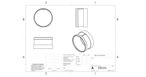
The drum volume is approximately 0.5L. The diagram below shows the basic design of the drum. The drum is designed to dry a small piece of clothing. It is also decided to rotate at a desired speed. Three different drum were designed by our team. The first one is an steel drum with no baffle. The second one is an aluminum drum with no baffle. The third one is an aluminum drum with 3 baffles in it. According to our analysis, the best design is the aluminum drum with three baffles. The aluminum drum has good thermal conductivity, which can help heat transfer to clothes easily. Also, aluminum has a high melting point and strong intensity so that we won't worry about the drum will damage. Moreover, as explained previously, the baffles make the drying efficiency improve significantly. However, due to technical problems, we had no choice but to give up this best design. We finally used the design which is aluminum without baffle. The final design is shown below.
Drive System and Motor Support
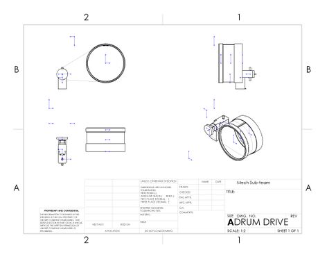
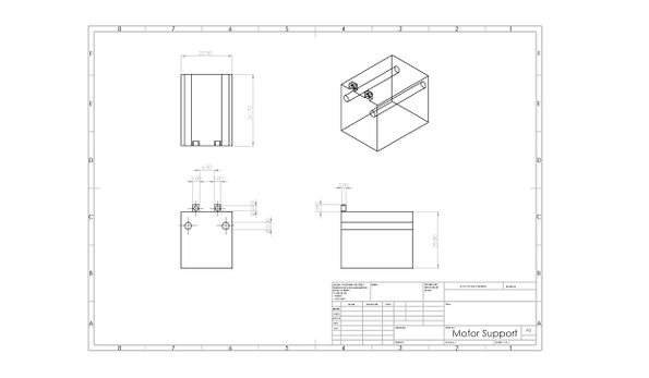
A motor will be used for the drum drive to provide rotation. The mounting position of the motor will be on the outside of the drum, on the bottom panel. A motor support is used to secure the motor while it is rotating the drum.
Heat Exchanger Top
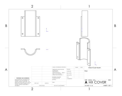
A heat exchanger top will be used to cover the heat exchanger and protect it.
Temperature and Humidity Sensor
A sensor will be used to monitor the temperature and humidity in the drum, in order to make the system control the heating temperature and time.

User-Interface Design
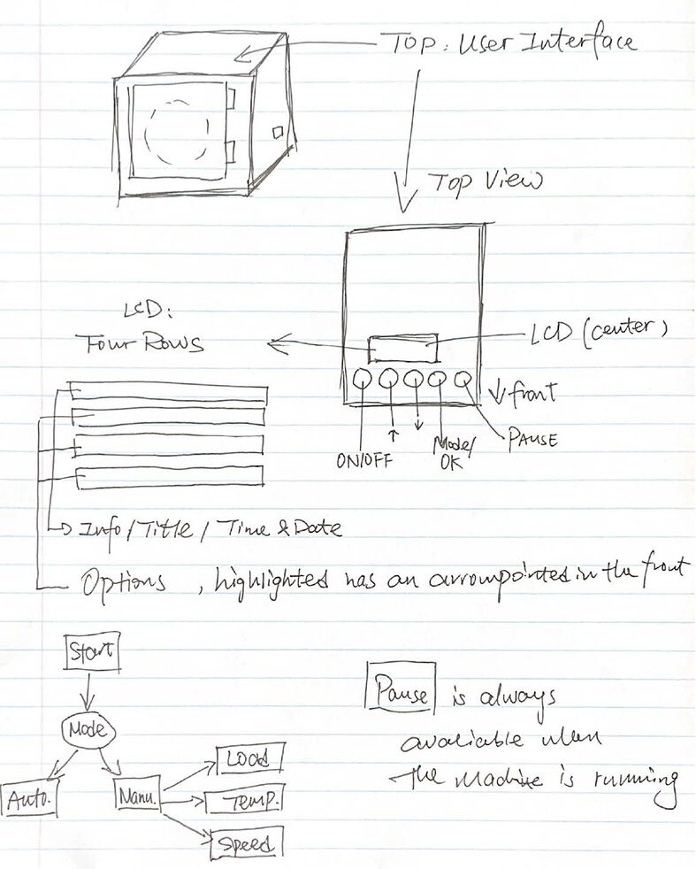
User Interface refers to the interaction between users and machine, such as changing settings or giving orders. It helps the users control the machine to satisfy their requirements. This is structured by five buttons and one LCD screen.Five buttons are distributed in one line horizontally with fixed distance between each two of buttons. Each function of the buttons from left to right are, “ON/OFF”, “UP”, “DOWN”, MODE/OK” and “PAUSE” respectively.
Requirements
Functions

Our UI design follows the following design specifications, and allows user to choose between "auto" and "manual" modes. "Pause" function allows user to pause the system and make changes.
Functions Comparison
Functions Comparison Table (PCC)
| Types of Clothes | Speed | Temperature | Weight of Clothes | Night Mode | Total Score | |
|---|---|---|---|---|---|---|
| Types of Clothes | - | 0 | 0 | 0 | 1 | 1 |
| Speed | 1 | - | 0 | 1 | 1 | 3 |
| Temperature | 1 | 1 | - | 1 | 1 | 4 |
| Weight of Clothes | 1 | 1 | 0 | - | 0 | 2 |
| Night Mode | 0 | 0 | 0 | 0 | - | 0 |
Objectives
- Users can interact with machine easily
- LCD displays information concise and easy-to-read information
- Users can pause the system and open the door
Constraints
- User can use control the machine
- No more than 5 buttons
- Must display necessary information on LCD
- LCD has to tell user the current machine status
- The machine must have auto and manual two modes
The Design
Hardware Layout
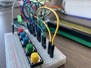
Hardware Final Design
Considering the cost and convenience, the final design of the user interface uses five buttons, one LCD, one LED and the Arduino to complete the circuit connection. The Arduino is used to receive input information and send the command. The LCD is to show the prompt message and different options, while the LED is used to indicate the status of the machine. The buttons are to help users to interact with the machine. The red button is ‘ON’ button which is used to turn on the dryer, and the blue buttons are ‘Back to Top’ and ‘Down’ buttons which are for users to choose options. The green button is ‘Mode/OK’ button, which is to confirm the option, while the yellow one is ‘Pause’ button to stop the drying. Following pictures shows the connection of the circuit.

Operating Sequence
After the machine is lightening up (when user push down the “ON/OFF” button), the screen will show our team “brand” first, and it will last for 5 to 10 seconds, depending on how long it will take to do a self-running check. After that, it will show the current date and time. Below these information, two rows of choices are displayed, “automatic” and “manual” modes are shown, automatic mode is selected by default, if the user click “MODE/OK” button again, it will start automatically by using automatic detect function to determine the weight of the clothes, the temperature it need, how fast will it run and an estimated time. If the users use “UP” or “DOWN” button to select “manual” mode, the screen will show menu in three sections, in the “Cloth Load”, “Temperature”, and “Speed” order, to let user decide which they would like to use. There are three or levels provided in each section, “HEAVY”, “MEDIUM” and “LIGHT” under the “Cloth Load section”; “HIGH”, “MEDIUM”, “LOW” under “Temperature” section; “NORMAL” and “QUICKDRY” are in the “Speed” section.
When user finish selecting, the machine will start to work, and show an estimated time on the screen. When the dryer finished one full cycle of drying, the screen will display “Done. Please open the door.”
When the door is detected as opened, the screen will back to the top menu, which is “automatic mode and manual mode”. When user finish selecting, the machine will start to work, and show an estimated time on the screen.
When the dryer finished one full cycle of drying, the screen will display “Done. Please open the door.”. When the door is detected as opened, the screen will back to the top menu, which is “automatic mode and manual mode”.
Final Display Demo Pictures
When the Arduino is connected with computers, the LCD will light up and show the group number, and the LED will not light up.
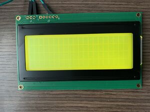
When the ON button is pressed, the dryer will be switched on. The LCD will show the Home page, and the LED will also be on.

After pressing the OK button, the LCD will show two modes which are Automatic and Manual. The Down button is used to choose the options. For the automatic mode, it will dry the clothes with fixed temperature and speed set by Electrical Team.

When users press the OK button, auto mode is confirmed. The LCD will show ‘Processing…’ to indicate that the dryer machine is running. For this mode, the remaining time cannot be seen.
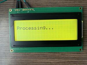
When Electrical Team detects that humidity is appropriate to end drying, it will send the signal to the user interface. When receiving the signal, the LCD will show the Finish page.

For Manual Mode, the users can set the Temperature, Speed and Cloth Load. The drying time is determined by three settings and is set to be able to dry the clothes completely.
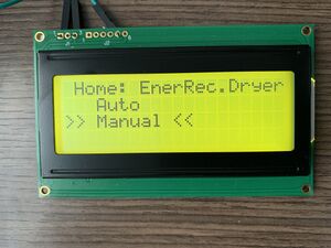
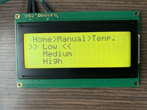
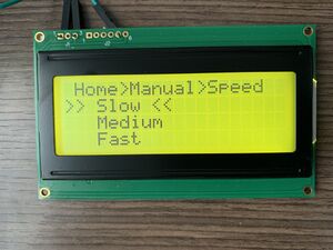
When entering this mode, Cloth Load, Temperature and Speed will be set in order. Cloth Load is from Light to Heavy, and each option indicates a number. 0 is Light, while 2 is Heavy. Medium refers to 1. After setting the Cloth Load, the page will jump to Temperature. Temperature is from Low to High. 0 is Low, 2 is High, and Medium refers to 1. The last setting page is Speed, which is from Slow to Fast. 0 is Slow, 2 is Fast, and 1 is Medium.

After the settings are done, the drying time will be calculated by the following equation. The unit of time is minute.
The next processing page will show the remaining time. When the remaining time gradually decreases to zero, the drying is finished. The following picture shows the processing page. When the drying is completed, the Finish page will be presented.


he last button which is ‘Pause’ button is to make the drying suspended. When pressing this button, the drying will finish immediately.
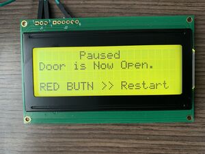
If E Team detects that the door is open, the warning page will be shown. The following picture is the Warning page. The title will blink to prompt user to pay attention. See the video attached to see the real warning screen.

To restart the drying, users can press "ON" button to turn on the dryer again.
Temperature and Humidity Sensor
Temperature and humidity sensor are owned by Electrical Sub-team, our program was designed to retrieve necessary data from the sensor, and determine when the screen shows "Finish Screen" when user using the auto mode.
Due to the impacts of Covid-19 pandemic , we were not able to assemble all parts together, so we cannot show real linkage between our program and Electrical group's sensors.
Program Flow Chart
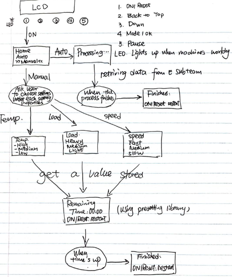
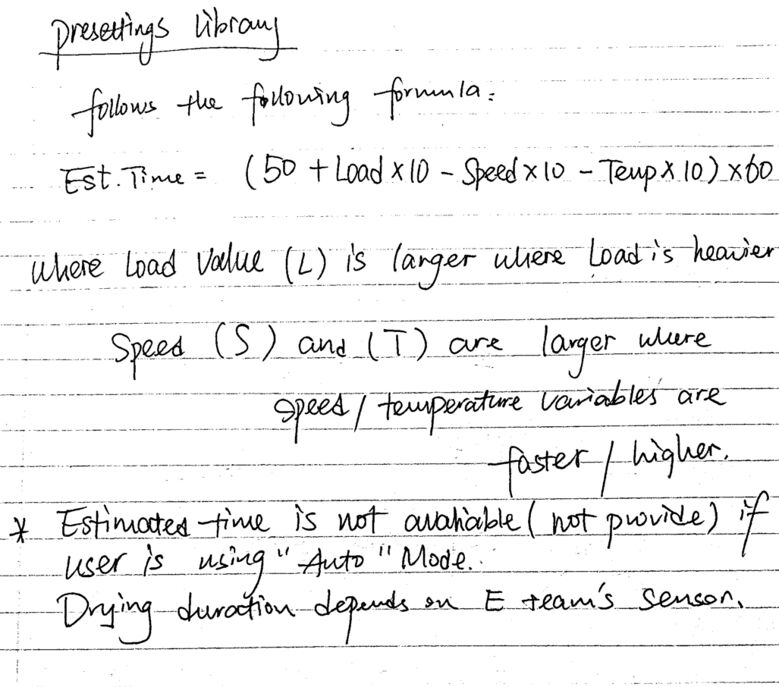
Our code is now available at Arduino Create webpage, you may see the full code at: https://create.arduino.cc/editor/futandrew/eb8a7120-159d-4d7e-8730-ea7f678320e8/preview
Means of Inputs
Our original design was after turning on the machine, there are three options shown on the LCD, which are time, temperature and speed. Time is the option to set the ideal drying time, which includes 30 minutes, an hour and 1.5 hours. Temperature is to set the ideal temperature in the drying process, and the levels are three from Low to High. Speed is to set the ideal rolling speed in the drying process, and the levels are also three from Low to High. Pressing four direction buttons, the cursor is moved to the ideal options, and then the users press OK button to finish the settings for one drying.
Using different buttons to control different options. For example, for temperature setting, three buttons named Low temperature, Medium temperature and High temperature are needed to tell which is the choice of the users. It means we need at least 9 buttons. Too many buttons and lines make the connection complicated. It is not only difficult for users to understand the meanings but also easy to break. So, we try to minimize the buttons. Through the guide of the tutor, we finally choose this five-button design. The four direction buttons are easy to locate the ideal options, and the OK button is to choose the options. It is convenient to use, and also helps decrease errors.
Special Scenarios
If the user did not follow the correct process, there are some scenarios:
- Door does not close: Prompt user to close the door to start
- No response for 10 seconds: Buzzer prompt user to continue, and LCD show corresponding information
- Door open without Pause: Buzzer prompt user, LCD show this information and stop the drying function
Structural Design
For the clothes dryer project, we are the member of the structure sub-team in the project, everyone is an integral part. In our team, there are six designed tasks for the project which focuses on the overall framework for the clothes dryer, which includes door opening, front and side door, LCD and buttons, water collection tray, aluminum frame and bottom panel.
Requirements
Functions
The functions of the structural sub-system are designing the overall framework for the clothes dryer, which includes door opening,front and side door, position for LCD and buttons, water collection tray, aluminum frame and bottom panel.
Objectives
The objectives of our design is to make an enclosure of clothes dryer (include door opening, water collection tray, LCD and buttons) with high convenience, safety and practicability. The clothes dryer should be portable and easy to use.
1. The clothes dryer is highly convenience and portable.
2. The opening door and basic structure of enclosure is highly safety.
3. The function of the LCD and buttons are easy to use and practicable.
4. The structure design of water collection tray has large storage space.
Constraints
The clothes dryer must be:
1. The door can be opened by user.
2. The LCD display can be found and easily read by user.
3. The buttons can be found and used by user to control the clothes dryer.
4. The water collection tray can collect water.
The Design
Enclosure
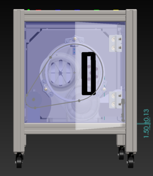
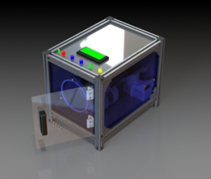
To design the clothes dryer enclosure, our team uses the SolidWorks to draw the 3D views for the clothes dryer.
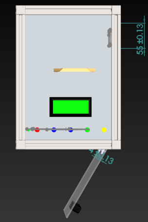
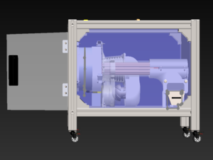

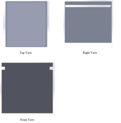
There are the three views of our design: a top view, front view, and the right view. In the top view of the design, there are five buttons for controlling the clothes dryer. The distance between the two buttons is 30 mm. The rectangle hole locates above the controlling buttons is the LCD, which presents the information about the time and temperature. The position is close to the controlling buttons because it can be convenient for the user to see the information for the dryer while making controls. In the front view of the design, the design for door opening is in the front position so that
the operator can put into or take out the clothes easily. In the right view of the design, there is a hole in the lower right corner. This hole is designed for the water collection tray, and the length and width of the hole are 40 mm and 40 mm, respectively.
Portability (Wheels)
There are four wheels placed on the bottom, each wheel is 360˚ rotatable, which allow user to move the clothes dryer fluently.
Door
The designing work of enclosure requires a comparison of different samples and consideration of the specific functions. To find a better design for the clothes dryer, our team investigated different clothes dryers in school residences and shops. There are three kinds of enclosure designs in the market: iris door, side swing door and sliding door. The Table below has been used to compare the characteristics of each design to confirm which design is more appropriate. The contrast of the enclosure arises from safety, operation time, cost and counter space.
| Weight (%) | Iris door (%) | Side swing door (%) | Sliding door (%) | |
|---|---|---|---|---|
| Safety | 35 | 10 | 70 | 20 |
| Operation time | 20 | 40 | 20 | 40 |
| Cost | 25 | 35 | 30 | 35 |
| Counter space | 20 | 40 | 20 | 40 |
| Sum | 100 | 28.25 | 40 | 31.75 |
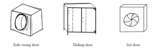
The best enclosure design is shown to be a side swing door. In the aspect of safety, our team believes that the door design for iris door or siding door has a greater possibility of getting caught in the process of operation. Moreover, we think safety is a significant factor for the design. So we give 35 percent weight to the safety. In the aspect of the operation time, we believe that the iris door and siding door can save part of the time during the operation. In the aspect of cost, we think that three different designs have similar costs for the projects. For the aspect of counter space, we believe that the side-swing door design will occupy a certain useful space in the drum. Based on the above considerations, our structure sub-team chooses a side swing door as the opening design of the clothes dryer.

Convenience (Handles)
Since the door opening is counterclockwise, a handle is located on the left side of the door, which allow user to open the door more easily. The handle for the door opening is used to help the operator to open the door easily. The four holes are designed for fixing the door opening with the clothes dryer.
Location of Control Panel
The control panel is consisted with LCD, buttons and LED., and it is on the top of the clothes dryer. To determine the best option for the position of LCD and buttons, our team considers two alternative positions for the LCD and buttons which are on the top of the clothes dryer and in the front of the clothes dryer. After conducting discussion and exchanging ideas with the user interface sub-team, we decided to use three standards to choose a suitable position for LCD and buttons: operational convenience, body appearance and durability. Table 3 has used to show the details about the position of LCD and buttons.

| Weight (%) | Top position (%) | Front postion (%) | |
|---|---|---|---|
| Operational convenience | 45 | 65 | 35 |
| Body appearance | 20 | 45 | 55 |
| Durability | 35 | 70 | 30 |
| Sum | 100 | 62.75 | 37.25 |
The suitable position for LCD and buttons is at the top of the clothes dryer. In the aspect of operational convenience, we believe that the option for the top position is better than the front position. Considering that the clothes dryer height is not high, the front position for LCD and buttons is not so convenient for the operator. In the aspect of body appearance, we think that these two positions are quietly similar. For the aspect of durability, we believe that the durability of the front position is not a good choice. Because if the door opening is designed in the front position, increasing the number of uses in the front position may damage LCD and buttons. Apply these three standards, we confirm that the top position is a better option for the LCD and buttons.

Convenience (LCD and Buttons)
LCD and buttons are placed on the top of the machine, which can save space for door and appropriately use the top surface of the clothes dryer. LCD is above the buttons; therefore, user can see the condition of the machine while controlling it.
Water Collection Tray
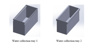
To determine the best design for the water collection tray, our team consider two different designs for the project. There are two standards for choosing the best design for the water collection tray, which are water capacity and stability. Water capacity refers to the volume of water that can behold at one time. The feature for stability refers to the degree of stability that it is drawn from the dryer. Table below presents the alternative design for the water collection tray.
| Weight (%) | Water collection tray 1 (%) | Water collection tray 2 (%) | |
|---|---|---|---|
| Water capacity | 40 | 55 | 45 |
| Stability | 60 | 65 | 35 |
| Sum | 100 | 61 | 39 |

In the comparison of two designs, water collection tray 1 has a larger capacity and better stability than the other. The water collection tray 1 has two grooves along two sides which allow the tray to move in and out of the drainage area without reducing the width of the water collection tray. The views of water collection tray 2, which uses the same principle but a different solution. However, the other design needs to reduce the width to fit the inner slots inside of drainage area so that capacity will be smaller. On the other hand, consider the size of the grooves, water collection tray 2 is a little bit oversize, which means it is hard to entrance and exist the grooves, the worse stability. Therefore, the water collection tray 1 is a more appropriate one in two designs. In the process of testing the water collection tray, there are many problems for the design to suit the clothes dryer.

After assembling the water collection tray with the clothes dryer, we find that we cannot take out the water collection tray. In that case, we observe the 3D views for the water collection tray to determine why we cannot take out the water collection tray. Initially, the water collection tray can not be pulled out due to a closed sidewall. We optimized the wall by cutting out an opening or interfere with the component inside the clothes dryer so that the water collection tray can come out.
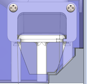
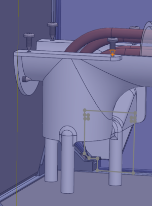
We find three reasons we cannot pull out the water collection tray. The first reason is that the corner of the right-side wall is the aluminum frame for the clothes dryer. And the second reason is that there are three pillars inside the clothes dryer. The third reason is that the tube inside the clothes dryer is circular, but the shape of the original water collection is a rectangle, this shape does not suit this tube. These three reasons hinder us from pulling out the water collection tray. According to this situation, our team decide to change the shape of the water collection.
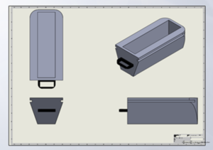
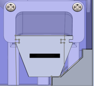
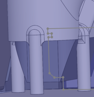
Our team decides to use the trapezoid as the shape for the water collection tray. This shape of the tray fits well with the wall, which is not in the way of the corner of the frame. In this version of the design, the water collection tray could be easily pulled in and out to recycle the water collected. The back of the tray is rounded so that its shape fits the bottom of the heat exchanger without blocking the three pillars that support the heat exchanger. Overall, we think the design has a pretty aesthetic look, and it fits will with the opening, which makes it our final design.

Electrical Design
Functions
The electrical and electronic team aimed to provide an electronic system to control the electrical components, including fans, motors, and heaters. These components aim to provide power and heat to tremble and dry clothes inside the drum. In addition to the controlling system, the electrical sub-team is responsible for the installation of electrical components and sensors.
Objectives
The primary objective of the electrical sub-system is to control each electrical component embedded in the clothes dryer to make these parts work in harmony. To help the dryer approach the highest working efficiency, the temperature will be set and fluctuate 10% at 55°C. This dynamic temperature will be alternated by the value returned by sensors. In addition to the temperature control system, the behaviour of the rotating drum will be controlled by the electrical system, including the rotating speed and directions. To reach the ideal heat transfer efficiency, the rotation rate is designed to fluctuate 20% at 30 rpm and the rate of airflow will is designed at 7.5 m/s. At this speed, the clothes can be heated uniformly.
Constraints
As the constraints of the electrical sub-team, the manual operating mode is able to customize the drying time, temperature and dryness of clothes inside the drum. Moreover, the program which controls the electrical components can adjust the temperature of the temperature and the rotating speed of the motor and fans directly based on different parameters according to the customized commands from users.
The design
Functions
Automatic Settings
As the electrical and electronic sub-system was called by the user interface subsystem, the electrical and electronic program starts running and works in automatic mode. In this mode, the users do not need to interrupt the task. The motor and fan will work at full speed. In addition, the algorithm of the PID controller makes the temperature of the system gently reach the desired temperature. If users want higher temperatures, they can change the working mode to manual mode in the UI subsystem.
Manual Settings
As the user wants to customize the setting of this clothes dryer, the user is able to select the manual mode in the UI subsystem. In this mode, the temperature as well as the speed of rotation can be customized. However, the speed of the fan embedded inside the dryer does not change and the fan still runs at full speed to make the thermal efficiency of the system as high as possible. There are two available levels of motor speed and three available levels of heater temperature in this mode. The electrical and electronic systems execute with different parameters of temperature and motor speed according to the returned value from the UI subsystem. As for controlling the heater, the algorithm of the PID controller is used as well in the manual mode to protect the system and maintain systematic stability.
Circuit Design
Power Supply
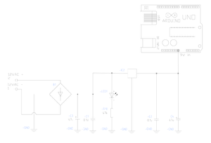
Considering the safety of users, 12V AC power adapter is selected for being the primary power supply. As can be seen from Figure, several electrical components are used in this electrical schematic, including LEDs, resistors, capacitors, and rectifiers, etc. The purpose of using LED is to show the working status of the power supply subsystem, which helps user know whether the power socket is plugged in or not. In this electrical system, a rectifier is used to convert alternative current to direct current and capacitors are used to smooth the humps of electric current. Considering the different required voltage of electrical components, the 12V AC power is converted to 9V DC power to support the Arduino platform and the fan. In addition, the heater is supported by 12V AC power.
Fan Circuit

The fan is connected to the digital PWM signal pin, which is able to adjust the speed of fans through the Arduino platform. The fan is powered by 9V DC which is the same as the voltage in the Arduino. A MOSFET component is used to switch and control the load of the electrical circuit. In addition to the circuit part of the fan control system, the software part uses parametric to call and control the fan to work at a specific speed. In the electrical program of this dryer, the speed of the fan is set at full speed to reach the highest thermal efficiency of the dryer, which conducts the heat flow as efficiently as possible.
Drum Motor Circuit

The drum motor is powered by 5V DC power and controlled through a PWM signal pin which is the 10th pin of the Arduino platform. Similar to the control system of fan, a MOSFET component is used to switch and control the load of the electrical circuit. The speed of motor can be directly controlled by setting different parameters in the Arduino program. In terms of control software, there are two feasible ways to rotate the drum, which are rotating in one direction and alternate rotation in both directions. The design of rotating in single direction will have less power consumption than the plan with switchable directions and has less loss on the motor. The second plan is to design a drum that can be rotated in switchable directions. Even though it will be more efficient to dry clothes by using switchable rotating direction, the stability is a more important factor to determine which plan is better to be selected. As can be seen from Table, the results of the evaluation of the two alternative designs are labelled.
| Weight (%) | First Plan (%) | Second Plan (%) | |
| Maintenance Rate | 70 | 70 | 30 |
| Drying Efficiency | 30 | 30 | 70 |
| Sum | 100 | 58 | 42 |
Heater Circuit
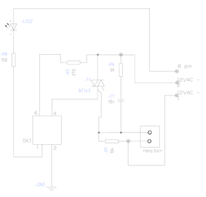
As the main part of controlling the heater in the electric circuit, an opto isolator is used to isolate the controller from the alternating current. This circuit is connected to a PWM signal pin, which is the 8th digital pin of Arduino. The heater is powered by 12V AC power. In addition to the circuit part, the heater is controlled by the Arduino platform. Since a sensor is connected in the circuit, the program is able to control the working status of the heater according to the value returned from the sensor. An algorithm of PID (Proportional Integral Derivative) controller was used to make the adjustment of temperature more precisely. This control logic will be introduced in the sensor session.
Temperature and Humidity Sensor

The temperature and humidity sensors are integrated into one single unit which has four pins to be connected to the Arduino and returns real-time values. Two of the pins are connected to ground and voltage in pins, respectively. One of the pins is connected to the analog-in pin of Arduino.
Considering the power saving features of the clothes dryer, the algorithm of the PID (Proportional Integral Derivative) controller was used, which automatically applies an accurate and responsive correction to a control function. This algorithm processes data returned from the sensors and calculates the error signal between the sensed value and desired value so that it can create a proportional gain effect of temperature. The PID controller can help to constantly adjust the duty cycle to keep the temperature close to the desired value gently. The ideal curve of temperature is shown in Figure.
| Weight (%) | First Plan (%) | Second Plan (%) | |
| Stability | 50 | 70 | 30 |
| Accuracy | 50 | 80 | 20 |
| Sum | 100 | 75 | 25 |
Extra Features (Door Status Detection)
In addition to the basic function of the clothes dryer, one additional feature was designed and integrated into the electrical system. To protect the safety of users of this clothes dryer, the status of the door is able to be detected. This feature is implemented through one switch which detects whether the door is closed or not. If the door is closed, the program of the electrical system will be in the normal working process. If the door is in the status of opening, the system will remain a PAUSE status, which will be sent to the user-interface subsystem to give further warning to users.
Virtual and Actual Prototype Demo
The following video shows the whole process of our system.
References
[1] E. E. S. Michaelides, “Alternative Energy Sources - Efstathios E. Stathis Michaelides - Google Books,” 2012. https://books.google.ca/books?id=-4wh16C7pEwC&pg=PA218&lpg=PA218&dq=fraction+of+the+household’s+energy+clothes+dryer+consume&source=bl&ots=633Ne5L-rW&sig=ACfU3U3XPRH8PpaUa8MkQrrQnMGT1k3yaA&hl=en&sa=X&ved=2ahUKEwiI25y09_XpAhWabc0KHbTDBOYQ6AEwAHoECAsQAQ#v=o (accessed Jun. 08, 2020).
Live Chat
We are on duty during capstone hours according to this roster:
Please chat with us through Collaborate Ultra
| Names | Day & Time (Vancouver) |
|---|---|
| Dingwen Wang & Yisheng Liu | Day 1 & 11:30AM - 12:30AM |
| Ansel Chen & Leo Cheng | Day 1 & 12:30AM - 1:00PM |
| Ansel Chen | Day 1 & 1:00PM - 2:00PM |
| David Zhang & Zhezheng Ren | Day 1 & 2:00PM - 2:30PM |
| David Zhang & Andrew Zhang | Day 1 & 2:30PM - 3:00PM |
| David Zhang & Zhezheng Ren | Day 1 & 3:00PM - 3:30PM |
| Zhezheng Ren & Leo Cheng | Day 1 & 3:30 PM - 4:00PM |
| Jinghan Gao & Lihao Xue | Day 1 & 4:00PM - 4:30PM |
| Lihao Xue & Bingyu Xie | Day 1 & 4:30PM - 5:00PM |
| Bingyu Xie & Jinghan Gao | Day 1 & 5:00PM - 6:30PM |
| Team 2 excused | Day 1 & 6:30PM - 7:00PM |
| Lihao Xue & Dingwen Wang | Day 1 & 7:00PM - 7:30PM |
| Lihao Xue & Yisheng Liu | Day 1 & 7:30PM - 8:00PM |
| Dingwen Wang & Yisheng Liu | Day 2 & 8:00AM - 9:30AM |
| Ansel Chen & Dingwen Wang | Day 2 & 9:30AM - 10:00AM |
| Ansel Chen & Yisheng Liu | Day 2 & 10:00AM - 10:30AM |
| Ansel Chen & Leo Cheng | Day 2 & 10:30AM - 11:30PM |
| Andrew Zhang & Leo Cheng | Day 2 & 11:30PM - 12:30PM |
| David Zhang & Zhezheng Ren | Day 2 & 12:30PM - 1:30PM |


