Team 1 Electrical
Requirements
Functions
- The user can set the time of operation, and the dryer(drum) will run the time entered by the user. (collaborate with User-interface team)
- The user can enter the "higher temperature" and "moderate". If the user choose high temperature, the heater will operate whole time. If the user choose moderate, the heater will operate in a period. (collaborate with User-interface team)
- The dryer can automatically adjust the temperature in the drum, achieved by the data from the Temperature/Humidity sensor.(collaborate with Mechanical team)
- When the temperature is too high or the dryer is paused, the operation light will be blinking, as shown in the video.
Objectives
- Connecting the Fan, Drum Motor, Heater and Temperature/Humidity Sensor in the circuit.
- The Fan, Drum Motor and Heater are connected on the breadboard.
- The Temperature/Humidity Sensor is located in the drum (refers to the Solidworks image in Mechnical section).
Constraints
- The spinning rate of the drum must be at least 90 spins/min
- A protective lock that when the door is open, the whole dryers must be shutted down immediately.
Design
Power Supply
The electrical sub-team mainly comprises of the fan, the motor, the heater, the temperature sensor, and the operation program of the clothes dryer. The Arduino board and the breadboard is used to connect and control the circuit.
The motor is used to operate the drum by transferring the rotation energy to the drum through gears. The temperature sensor is assembled inside the drum. When the operation starts, the operating light turns on (LED 1), coming with the fan, the motor, and the heater. When the fan is on, the drum is ventilated. As the temperature reaches a threshold temperature, the heater stops, the light blinks. When the start button is pressed, the dryer is required to work in a cyclic process as shown in the work diagram until it reaches the time user entered. The user can pasue the drum, and the heater will keep doing on and off so that the light connected to the heater will be blinking. It provides a siganol and keeps the temperature as stable as possible. The code is shown in the code category.
Fan Circuit
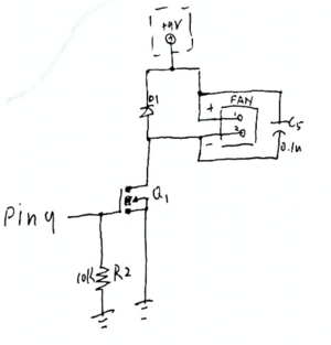
As shown in this figure,
the pin 9 from the Arduino is the output and a 0.25w resistor is connected first. After then a mofset is connected, the S side is connected to the ground and the other side connects a dionode, a fan and a 0.1u ceramic in parellal. These are powered by the 9V relating to previous diagram.
Drum Motor Circuit
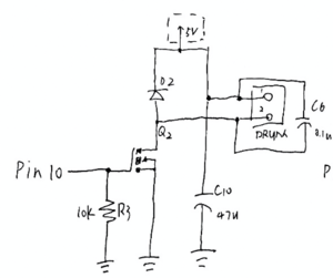
The motor has the similar principle as the fan with an additional 47u electrolytic capacitor, but the output is from pin 10.
Heater Circuit
The circuit is connected to pin8 with a 0.25w resistor and a triac. The safety capacitor and a 0.25w resistor, a 0.25w resistor and LED, and a 0.25w resistor are connected in parellel. The LED lights on when the heater is working.
Temperature and Humidity Sensor
The sensor is connected on the heater circuit. Whether the circuit is closed or opened depends on the temperature it measures. For example, if the sensor detected that the temperature is higher than a threshold, the heater stops work.
Arduino operation code
The preferencetime, tempmin and tempmax refers to the output from UI subteam that user’s input. The blue button is pressed to pause the dryer, and the time stops. If it is pressed, the heater keeps on and off, to keep the temperature in the drum and the connected light provides a signal.
#define heater 8
#define fan 9 // fan connected to PWM pin 9
#define motor 10 // motor connected to PWM pin 10
void setup() {
pinMode(8, OUTPUT);
pinMode(9, OUTPUT);
pinMode(10, OUTPUT);
}
void loop() {
if(bluebutton==OFF){
for (timer=0; timer<preferencetime; timer++){
if(analogread(temp)<tempmin){
analogwrite(heater, HIGH);
}
if(analogread(temp)>tempmax){
analogwrite(heater, LOW);
}
analogWrite(fan, HIGH);
analogWrite(motor, HIGH);
Delay(1000);
}
If (bluebutton==ON){
analogwrite(heater, HIGH);
Delay(1000);
analogwrite(heater, LOW);
Delay(1000);
}
}


