Course:VANT151/2020/Team1/Team1Main
VANT 151 Team 1 Wiki
Home
Welcome to VANT 151 Team 1 Wiki Page!
Project Objective
The objective of this program is to design and build a scale-down prototype of an energy recovery clothes dryer.
Group Information
There are 10 members and 5 sub-teams in Team 1.
Documentation: Report, Poster, and PowerPoint.
Electrical: Electrical Structure, Heater, and Programing.
Mechanical: Drum Drive, 3D designing, CAD File, and Heat Exchanger Design.
Structural: Structure Design and Anime & UI CAD.
User-Interface: Operation Programing, Electrical Connection.
User-Interface Design
Requirements
Functions
The functions of the user-interface sub-team are making the buttons read users’ input which represent each choice.
Different instructions need to be displayed on the LCD screen when any of the three buttons is pressed by users.
The LCD should be able to display messages.
If the message is long, the LCD should be able to scroll left and right to ensure that users can read each word clearly.
Objectives
The objectives of the user-interface sub-team are to display messages of the function of each button in each step. For example, the message required users to start the dryer will be displayed at the beginning.
When the dryer is working, the remaining time will be displayed on the screen and the time will be counted down.
After the dryer finished working, the buzzer will make a sound to remind users to take out the things in the dryer.
A 10k ohms potentiometer is also used to adjust the brightness of the LCD.
Constraints
The delay time between each step should be at least 10 seconds. A long delay time enables users to have enough time to make decisions.
Second, thick wires and resistors should be used for safety. The current in the wire may be large if there are any wrong connections on the breadboard.
In addition, the message should be displayed at the center of the LCD screen & the messages should be scrolled left and right. (The screen may be too small for all the messages shown on, so the message should be scrolled left and right repeatedly in order to enable users to see all information clearly.
The design

Hardware Layout
The system of the cloth-dryer is designed to contain LCD, three buttons, and switch to allow the user to interact with the machine.
The user can turn on and off the dryer using the switch.
The three buttons are utilized to make the user input their preferences and operate the machine accordingly to the user inputs.
The LCD to display the system
Operating sequence
The starts and end operations of the dryer depending on the mode whether it in manual mode or automatic mode.

If the user turns on the switch and choose the manual mode, the dryer will operate for a specific time that is chosen by the user, and once the time passed, the dryer will turn off automatically.
If the user turns on the switch and choose the automatic mode, the duration of drying the cloth will depend on the air temperature that the sensor measures outside the dryer to confirm that the cloth is dried, once the sensor reaches the set temperature and humidity reading, the dryer will turn off automatically.
Temperature and Humidity
For the manual mode, the temperature and humidity to dry the cloth are stabilized, and there are two options for the user to choose which are hot and moderate.
For the automatic mode, the sensor is used to measure the outside air temperature and humidity of the dryer. This process is continuing until the sensor reads the set temperature to confirm that the cloth is dried then the dryer stopped to work.
The Flowchart Program
Mechanical Design

Requirements
Functions
The energy recovery clothes dryer can dry clothes efficiently and run stably.
Objectives
1.To design following mechanical components:


Drum: The main component of the dryer in which the clothes be placed and heated.
Motor Support: This component can hold the motor inside the dryer.
Drive Mechanism: To connect the drum with the motor for rotation mechanism. Sensor Mount: The position in which the temperature and humidity sensor should be placed.
Heat exchanger cover: A top cover of the heat exchanger.
2. To draw CAD files of several EE components.
Constraints
1. The drum should have at least 0.5 L capacity.
2. The mechanical components should be placed in a dryer that doesn't exceed 250×220×300 mm.
3. The motor support should be able to hold the motor and the design is suitable for the bottom of the motor.
4. The sensor mount should be suitable for sensor design and dimensions.
The Design
Drum Size


The final design for the drum size is a drum that have a large diameter and small size. This size will have a larger capacity for clothes. According to the capacity equation:

Where V is the volume, L is the length, and r is the radius.
As the radius is squared, the larger the radius, the larger the volume or the capacity of the drum. Since the size of the whole dryer can not exceed 250*220*300 mm, so we choose 110 mm radius and 100mm length as parameters of the drum. The volume of the drum is 3801.3 cm3 . Therefore, the capacity of the drum is 3.8013 L. The below diagram Figure 1. shows the basic design for drum.
Also, this design will be easier in rotation through the belt and pulleys as there is less surface to contact with the pulleys and thus easier in control. Additionally, this size is suitable for the dryer design to be placed inside. Based on this evidence, this size has a better performance than the alternatives.
Drive mechanism
The final design we choose for the drive mechanism is Belt and Pulleys, which composed of one pulley and one rubber belt, as shown in following Fig2. and Fig 3.
The pulley is attached to the drive motor and the belt is around the drum and the pulley to connect them. In this design, the motor is set away from the drum by means of a continuous belt loop, which means that the connection between the motor and the drum is indirect. This can minimize the vibration of the dryer during operation and other problems, which may result from vibration such as wear, noise, low lifetime, and others. This design also has a low production cost since the belt is very cheap and the mechanism has a simple structure.
Motor Support
The final design for the motor support is a triangular stand with plastic material. The triangular structure of the stand can provide better stability than the other four types of supports. The plastic material makes the support to be cheaper and lighter than steel. The stand is attached to the motor through 2 supports as shown in figure 4.
Heat Exchanger Top


A standard design for the tail of the heat exchanger as shown in figure 6.
Temperature and Humidity Sensor
For safety, the sensor shouldn't be too close to the heater and it shouldn't be inside the drum since there might be water. Thus, the starting part of air exhaust tubes should be the best place for measuring the temperature and humidity inside the drum. The final design for the sensor mount is installing the sensor in the exhaust ducts of the dryer near the area of the suction of the air blower. In this position, the sensor can measure the temperature and humidity of the air effectively. The sensor mounting is shown in Fig 5.
EE Parts CAD
The EE components' CAD files are shown in the merged figure to the right.
Electrical Design
Requirements
Functions
- The user can set the time of operation, and the dryer(drum) will run the time entered by the user (collaborate with User-interface team).
- The user can enter the "higher temperature" and "moderate". If the user choose high temperature, the heater will operate whole time. If the user choose moderate, the heater will operate in a period (collaborate with User-interface team).
- The dryer can automatically adjust the temperature in the drum, achieved by the data from the Temperature/Humidity sensor (collaborate with Mechanical team).
- When the temperature is too high or the dryer is paused, the operation light will be blinking, as shown in the video.
Objectives
- Connecting the Fan, Drum Motor, Heater and Temperature/Humidity Sensor in the circuit.
- The Fan, Drum Motor and Heater are connected on the breadboard.
- The Temperature/Humidity Sensor is located in the drum (refers to the Solidworks image in Mechanical section).
Constraints
- The spinning rate of the drum must be at least 90 spins/min
- A protective lock that when the door is open, the whole dryers must be shut down immediately.
The Design
Power Supply
The electrical sub-team mainly comprises of the fan, the motor, the heater, the temperature sensor, and the operation program of the clothes dryer. The Arduino board and the breadboard is used to connect and control the circuit.

The motor is used to operate the drum by transferring the rotation energy to the drum through gears. The temperature sensor is assembled inside the drum. When the operation starts, the operating light turns on (LED 1), coming with the fan, the motor, and the heater. When the fan is on, the drum is ventilated. As the temperature reaches a threshold temperature, the heater stops, the light blinks. When the start button is pressed, the dryer is required to work in a cyclic process as shown in the work diagram until it reaches the time user entered. The user can pause the drum, and the heater will keep doing on and off so that the light connected to the heater will be blinking. It provides a signal and keeps the temperature as stable as possible. The code is shown in the code category.
Fan Circuit
As shown in this figure,

the pin 9 from the Arduino is the output and a 0.25w resistor is connected first. After then a mofset is connected, the S side is connected to the ground and the other side connects a dionode, a fan and a 0.1u ceramic in parallel. These are powered by the 9V relating to previous diagram.
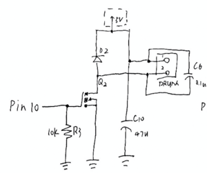
Drum Motor Circuit
The motor has the similar principle as the fan with an additional 47u electrolytic capacitor, but the output is from pin 10.
Heater Circuit
The circuit is connected to pin8 with a 0.25w resistor and a triac. The safety capacitor and a 0.25w resistor, a 0.25w resistor and LED, and a 0.25w resistor are connected in parallel. The LED lights on when the heater is working.
Temperature and Humidity Sensor
The sensor is connected on the heater circuit. Whether the circuit is closed or opened depends on the temperature it measures. For example, if the sensor detected that the temperature is higher than a threshold, the heater stops work.

Arduino operation code
The preferencetime, tempmin and tempmax refers to the output from UI sub-team that user’s input. The blue button is pressed to pause the dryer, and the time stops. If it is pressed, the heater keeps on and off, to keep the temperature in the drum and the connected light provides a signal.
#define heater 8
#define fan 9 // fan connected to PWM pin 9
#define motor 10 // motor connected to PWM pin 10
void setup() {
pinMode(8, OUTPUT);
pinMode(9, OUTPUT);
pinMode(10, OUTPUT);
}
void loop() {
if(bluebutton==OFF){
for (timer=0; timer<preferencetime; timer++){
if(analogread(temp)<tempmin){
analogwrite(heater, HIGH);
}
if(analogread(temp)>tempmax){
analogwrite(heater, LOW);
}
analogWrite(fan, HIGH);
analogWrite(motor, HIGH);
Delay(1000);
}
If (bluebutton==ON){
analogwrite(heater, HIGH);
Delay(1000);
analogwrite(heater, LOW);
Delay(1000);
}
}
Structural Design
Requirements
Objectives
- Enclosure: The outer frame of the dryer which contains all of the components.
- Openings: The holes on the enclosure which will be used to place LCD and control buttons.
- Door: The door of the dryer
- Water tray: A container that used to collect water.
Constraints
- Convenience for users: the structure can be easily achieved by the users.
- Capacity: the space inside the enclosure should be big enough to contain all of the components.
The Design

Enclosure
| Standard cubic design with equal height and depth | large height & small depth | small height & large depth | |
| Capacity | S | 0 | 0 |
| Convenience | S | -1 | +1 |
| Sum | S | -1 | 1 |
The final design for the enclosure is the design with small height & large depth. This size will be more convenient for the users to use. There is no big differences of the capacities of the two designs. There are all designed to have enough spaces for the drum drive and other components. However, the convenience of two designs are very different. The design should be convenient for users and can easily fits users’ home. Usually, users put the dryer machine on the top of the washing machine or in the shelf. It may be too high for the users to approach and use if the dryer machine has large height and it even will not be able to put in the shelf. Users may have to buy a new shelf to put the machine inside. With small height and large depth, the dryer machine can be easily approached and used. The machine can fit
users’ furniture easier. Therefore, we selected the design with small height & large depth.
Openings

When we choose for the location of the openings on the enclosure, we main focus on one point, convenience for the users. The LCD screen should be easily seen by the and the control buttons should be easily be approached by the users to avoid miss operations. When the machine is individually placed on the ground, there is no significant difference between the convenience of the two designs. However, when it is placed on the washer machine, which is very possible, the design with openings on the front side will be much more convenient. When being placed on the washer machine, the design with openings on the top will not be very easy to use. It may be too high for the users to see the screen or press the buttons. Users may need to use a chair to help them which is dangerous. When people can’t see the screen and buttons, they will be likely to have miss operations. The design with openings on the front side will not have those problems. The screen can be seen by the users easily and clearly as well as the control buttons. Therefore, there will be less miss operations. Thus, we choose the enclosure with openings on the front side as our final design.


Door
We designed a rectangular door as the final design. Currently, there are two popular shape of dryer door. One is circle, the other one is rectangular. According to the interview, more people prefer to use rectangular door. Moreover, when open a rectangular door, it has more space for people to put in or take out clothes. Therefore, we choose rectangular as the final shape.
Water Tray
For water tray, we designed a container to collect water. We plan to set it at the bottom of the dryer as people could pull it out easily. It shapes as a circle is mainly because our door is rectangular, we would like to make some difference since different shape will not influence the use too much.
Virtual and Actual Prototype Demo
Video 1
This is a video of UI display. The first one is manual mode, which displays the temperature, time and speed. The second one demonstrates the automatic mode, and everything is set in automatic mode.
Video 2
This is the animation of the CAD file of the project.
Live Chat
The live chat url is shown below. You can also contact us via our contact informations.
| DAY | TIME | Presenter | Presenter | Presenter |
| DAY 1
13 JULY 2020 |
11:15 – 13:15 | Sara | Menna | N/A |
| 13:15 – 15:15 | Kehan | Qichun | ||
| 15:15 – 17:15 | Yining | Eric | ||
| 17:15 – 19:45 | Yuyan | Alex | ||
| DAY 2
14 JULY 2020 |
8:00 – 10:00 | Will | Brad | |
| 10:00 – 12:00 | Menna | Alex | ||
Team Members
| Documentation | |
|---|---|
| Kehan Zhang
Student Number: 57828832
Contact Information: zhangkh2001@gmail.com My name is Kehan Zhang, I'm in the documentation sub-team in Team 1. I did most of the report and the whole organization of the presentation. I am also responsible for the overall structure of the website. I learned a lot from this course, including how to communicate with team members and how to group work. |
Yuyan Huang
Student Number: 15811615 |
| Electrical/Electronic | |
| Alex Xu Student Number: 55867857
Contact Information: alexxu_cn@outlook.com In the Electrical team, I mainly responsible for communicating and discussing the problems with other team members, and help Will finish our goal. We negotiate very well and we solve problems together. |
Will Yang
Student Number: 46906210 Contact Information: Yang.Xinchao@outlook.com In a paragraph, say who you are, state your contributions to the project and mention something relevant that you learned from the experience. |
| Mechanical | |
| QICHUN SHEN
Student Number: 16568602 Contact Information: songgangalbert@163.com I participate in the designing for drive mechanism, drum size, motor support and sensor mounting. I also participate in the SW drawing of the heat exchanger cover and the editing of the webpage. |
Sara Mohamed (Team Leader) Student Number: 95590519
I love Graphic design, traveling, and trying new things. I have contributed to this project by managing the tasks of the team and supervising the work. Also, I have contributed to the Mechanical sub-team tasks such as the process of drafting and choosing the appropriate designs, and designing the motor support, drum drive mechanism animation, and EE parts in SolidWorks. . |
| Structural | |
| Brad QiangStudent Number: 98540818
Contact Information: zejunqiang@163.com I am a member of the Structure Design sub-team in Team 1. I am responsible for using Solidworks to make the enclosure, the LCD screen snd the openings of the dryer. With the experience of this project, I learned how to have good and timely communications and cooperations with teammates who are from different countries and even staying in different time zones. |
Eric Zhang Student Number: 77150779
My name is zehong zhang. I am in the Structure sub-team in Team 1. I am mainly responsible for writing part of the report, building doors, water trays and buttons Solidworks. I improve my SOLIDWORKS skill in this project and realize the importance of cohesion in a team project. |
| User-Interface | |
| Mennatalla ashraf Mohamed Abdelrahman AKL Student Number: 14819759
Contact Information: mena.akl@yahoo.com My name is Menna. I’m from Egypt but I raised in Kuwait City. I’m a member of the user interface sub-team, which aimed to create a design that allows the user to interact with the dryer using buttons and LCD. I had a good experience working on that project because I learned how to create a design that is comfortable for the user to use and it is considering all abilities of people. |
Yining Zhong
Student Number: 84198362 Contact Information: zyning1118@outlook.com My name is Yining Zhong. I am in the user-interface sub-team in Team 1. I am responsible for writing part of the report, connecting the wire on the breadboard writing part of the code. Throughout this experience, I have learned how to communicate with my partner and solve the problems with patience. |


